
 A lot of interesting instruments created in radio school of the Gomel Palace of pioneers and schoolchildren named after V. I. Lenin. Here are some of them: pulse the flash and the instrument for testing high-power transistors developed by members of the group Valery Denisenko and Sergey Skruzny.
PULSE FLASH
works in conjunction with conventional incandescent lamps, is enabled at high voltage. However, if the lamp is designed for a voltage of 127 V, turn on 220 V, it will last no more than 15 min. But enough to reduce the burning time of the lamp up to 0.2 s and the filament can withstand several thousand inclusions. This fact is used in the flash unit, the circuit is shown in figure 1.
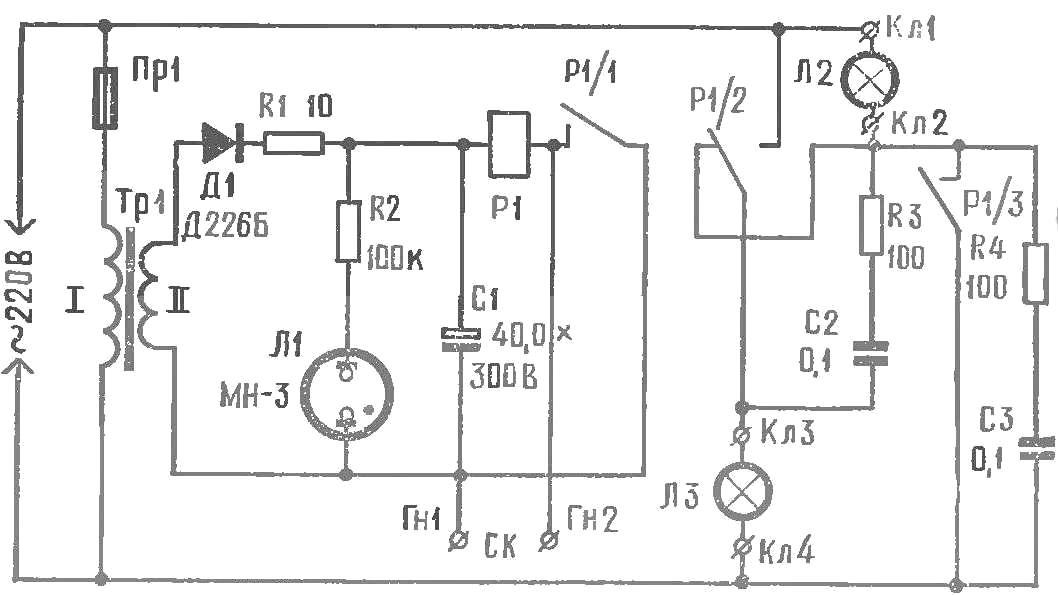
Fig. 1. Schematic diagram of the flash.
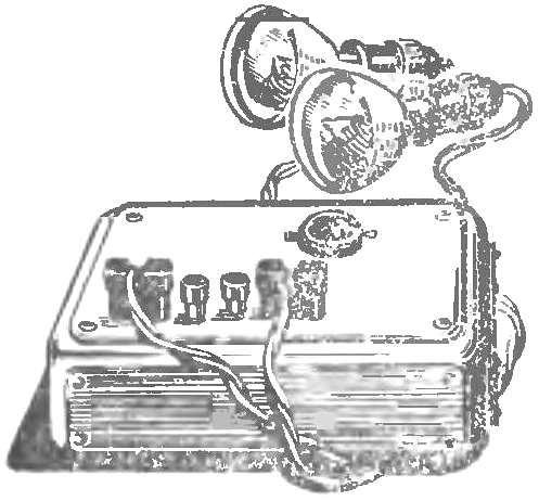
Fig. 2. The appearance of the flash
Transformer TR1 is wound on the core of the plates Ш12, the thickness set to 35 mm. the Primary winding has 2640 turns of wire of PEL 0,1, secondary — 1524 round of PEL 0,15. R1 — electromagnetic relay with a coil resistance of 5000 Ohms. Details of the scheme are mounted on the chassis, placed in a plastic or metal housing (Fig. 2) on the front panel which is equipped with terminals and sockets for connection of lamps and camera (IC).
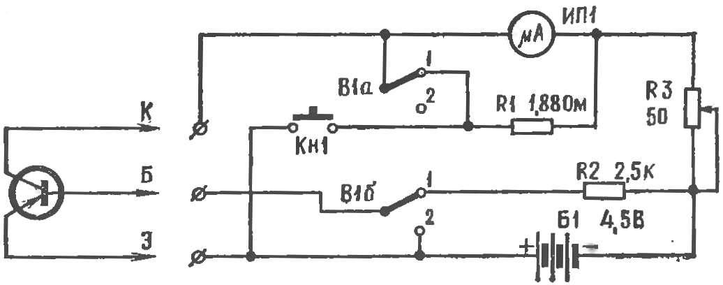
THE INSTRUMENT FOR TESTING HIGH-POWER TRANSISTORS
allows you to measure gain, reverse and initial collector current of transistor type A4, П201, П203, П216.
Assembled device based on the pointer. Current full deflection — 1 mA. Transistor is connected to the terminals КБ9 (Fig. 3).

Fig. 3. Diagram of the device for checking the power transistors.
To measure the gain coefficient β, the switch Q1 must be installed in position 1. In the 2-position toggle switch B1 is measured, the initial collector current. The scheme in this case will be switched so that the milliammeter is included in the collector circuit without the shunt, and the findings of the emitter and base shorted.
The reverse current of the collector transition is measured also in position 2 of the switch Q1, turning off the output transistor emitter from terminal E.
The device is powered from a single battery 3336L.
Recommend to read
 FOR BUSINESS AND TRAINING…
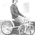
This bike has unusual pattern and drive: two steering wheels, instead of rotating the pedal — levers. The force on the chain is transmitted when a cyclist privste from the saddle. And of...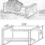 TABLE SHELF
Book required at the moment for work, must be always at hand; however, the folded stack on the table, they interfere, and use them uncomfortable. Make a simple table shelf, and you'll...
