When he stops, receives a return signal. The chain in its passage similar to the previous one. Thus, pressing the button of your machine, you control and operation of the apparatus at the opposite end of the line.
It is clear that the value of resistance of the connecting line (depending on the length, cross section and material of the wire) will significantly affect the mode of excitation of the generators. To compensate for this effect the resistor R2 (R21), which together with the diodes V1 (V11) perform the function of current distribution. Therefore, before to connect the devices to the line, the sliders of variable resistors set to the rightmost position according to the diagram (maximum resistance). Then, taking cues partner, set using the variable resistor of the device the maximum volume and the most pleasant tones. The same setting is carried out at the opposite end of the link. The apparatus is ready for operation.
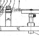
Fig. 3. Wiring diagram of the apparatus.
You can include in the overall and 3-4 of the machine. However, it must be borne in mind that the difference in the resistances of the lines should not exceed 1 -2 ohms.
And now about the design and details of the device. Dynamic head, button and variable resistor mounted on the front panel of a small-sized transistor radio. In this place the mounting plate (Fig. 3) made of foil Micarta or fiberglass with a thickness of 1,5—2 mm, and a galvanic cell. Clamps for connecting communication lines of any type, it is mounted on the side wall of the housing.
In a Telegraph device, you can use transistors series КТ306, КТ342, KT315 (n-p-n) and МП39-МП42 (p-n-p) with gain h213≥30 and preferably with a small current Ikbo ; diode type D2, D9, D20. Constant resistors — MLT-0,5, variables of any type with a resistance of 5.1 to 10 kω. Microswitches — MPZ, МП7 or the like. Dynamic head is calculated for a power of 0.1—0.25 W , has a voice coil resistance of 6-10 Ohms.
E. SAWICKI, Korosten, Zhytomyr region.
Recommend to read
 LATHE ON WOOD
Winds on the cutter scented shavings. And from small billets emerge the contours of a rolling pin, tolkushkoy, arm day hand tools... there are all sorts of useful things you can do with...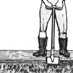 THE PATCH… ON THE LAWN
Now suburban suburban areas are very popular green lawns, pleasing to the eye a beautiful grassy carpet. However, they require proper care and maintenance, the complexity is almost equal...

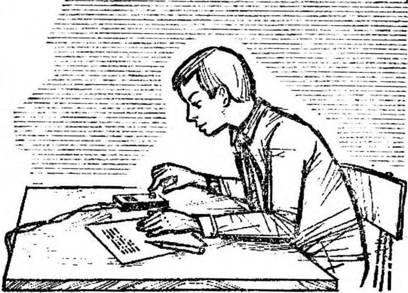 It’s tempting to assemble a simple Telegraph device and to communicate using Morse code. Reliable two-way communication is needed in the conduct of military sports games and competitions, in a tourist campaign and in summer camp, it is interesting to set it up at home or at the cottage.