ON ONE WING

ONE WINGNot for the first ten years there is a class of experimental aircraft. It would seem that this time is sufficient to clearly determine the best scheme inflected wing”, the most favorable profiles and types of balancing. But every new competitions at the Tushino airfield, gathering creative enthusiasts from all over the country, convinced that the search is not yet complete. And it is not surprising to achieve stable flight model “flying wing” in contrast to the classical devices are very difficult. Why so few “highs” in the tables of experimental results, although at first glance the benefits seem obvious tailless.

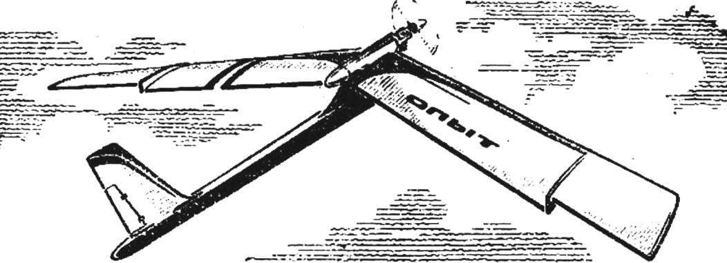
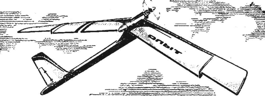
Today we introduce you to one of the latest designs of Russian Modeler Yuri Petrov. In General is not a new scheme Tierney experimental model with a straight wing sweep, and a tractor propeller with meticulous fine-tuning allowed us to achieve the main thing — stability results of operations.
 
The fuselage Tierney consists of two parts — the front, the power, and the tail boom. The Foundation of the first pylon, on it are mounted all the elements of the fuselage. It is made of plywood with a thickness of 8 mm, after treatment in the blank Windows of relief plastered on both sides millimeter plywood. Then the workpiece is filing the contour and glue fixed pine slats with a cross section of 10X4 mm — the longerons of the tail boom. She, along with the lower part of the pole is sheathed in a dense balsa with thickness of 3 mm. At the rear of the beams installed the balsa keel with a slight adjustment of the rudder. In the upper part of the pylon is glued into the two pin mounting wing panels. Short front (auxiliary) — beech Ø 4 mm; the back that takes all the load from the bend of the wing, the off — cut steel wire grade optical fiber Ø 5 mm. Before gluing the pylon he bent to put on his consoles transverse V was equal to 8°, then the middle of the wrapped thread, impregnated with epoxy resin, on the resin pin is tightly inserted into the corresponding hole of the pylon.
the upper horns of the bow by means of “epoxy” mixed with sawdust, fixed thin-walled metal tube (Т40Х1). It will allow simple and reliable” but mounted on the model engine with aluminum engine mount and fuel tank. The caudal extremity of the pipe is closed balsa tube-fairing.
 
The wing has an unusual rib — glass fibre laminate. This material is 0.3 mm thick metal profile templates, tapered contour at 1 mm, cut stacks of ribs for consoles and “ears” of the wing. The use of glass fiber (by weight of the sheet equal to the same veneer thickness 0,5—0,6 mm) allows you to form rigid, lightweight and durable wing. In an extreme case, the ribs can be cut from mm plywood. Profile consoles classic PLANO, the “ears” have the profile with the modified tail. The upper image is carried out parallel to the hem, pair tail sock is made from the bottom circle curve.
 
Fig. 1. Timer experimental aircraft
 
Fig. 1. Timer experimental models:
 
1 — motor, 2 — motor, 3 — tube pole, 4 — pole, 5 — tail boom of the fuselage, 6 — timer, 7 the rudder, 8 — Kiel, 9 — rear wing attachment node, 10 — node front hinge wing 11 — console, 12 — swivel 13 — edge 14 — the “ear”.

 
Fig. 2. The nose of the fuselage
 
Fig. 2. The forward fuselage:
 
1 — peel, 2 — tube pylon, 3 — root rib console, 4 — pin rear hinge wing 5 — tube console, hitch, 6 — rib, 7 — fairing, 8 — spars of the tail boom, 9 — trim I-beam, 10 — wire ski 11 is the covering of the pylon, 12 — pin front hinge wing.

 
Fig. 3. Mounting
 
Fig. 3. Mounting “ear” on the console:
 
1 — leading edge, 2 — hook, rubber strap, 3 — rib, 4 — rib shelf, 5 — rubber band, 6 — tube-axle, 7 — shelf spar, 8 — spar wall, 9 — edge 10 — hook machine, 11 — nylon fishing line machine, 12 — trailing edge, the 13 — adjusting screw 14 — dry 15 — rear hook a rubber strap, 16 — tube-bearing, 17 console, 18 — “ear”.

 
Unusual and leading edge, which is a dural tube with an outer Ø 3 mm pine Spars (5X4 mm) with a wall of balsa across the span, balsa rear edge has a constant cross-section 20X6 mm. After Assembly on flat boards, the stocks frameworks of the consoles and the “ears” on all rib glass fibre laminate shelves superimposed strips of balsa cross-section of 5X1 mm. In pre-drilled holes are pasted dural tube: Ø 7X1 in the root part of consoles for mounting of the wing on the pylon, Ø 8×1 to the ends of the consoles — this will be the hinges of the hinge “ears”, in the last — Ø 6X1. All end ribs from balsa, only the root is bogus, a thickness of 4 mm balsa plate of the same thickness made of the rib hindering the flow of air flow from the center section to the wing tips. These ribs are attached to the breadcrumbs under the adjusting screws M3 used for installation of angle of attack “of the ear” hooks of attachment of rubber bands, lifting the tails end sections of the wing when triggered, the machine forced landing. In the root rib of the “ears” are glued ka resin for two of the same hook from the sheet duralumin for the second end of the rubber harness, and for mounting a nylon fishing line machine planting. The finished wing is glued on amalite macalintal paper to the spar on the forehead in two layers. Connector center to edge glue the wire hooks on which the Assembly model of wound rubber thread.
Powerplant. At dural Motorama four screws mounted engine with working volume of 2.5 cm3 (compression had a good performance option “Meteor”), the Exact angle of the axis of the propeller down, will have to recruit during training, placing paws, motor V-strip.
 
Motor mount is mounted on the tube of the fuselage with three M3 screws with countersunk heads. Holes are in these two parts it is better to mark, drill and cut Assembly. Just behind the engine mount in the cavity of the pipe is a round tin can fuel tank. From the offset it back protects the horn of the pylon.
 
Fig. 4. The position of the
 
Fig. 4. The position of the “ear” after triggering the automatic forced landing.
 
Fig. 5. The nose of the fuselage
 
Fig. 5. The forward fuselage:
 
1 — motor, 2 — tube pylon, 3 — tube manifold 4 fuel tank, 5 — fuel tube, 6 — a feeding tube, 7 — retaining screw (3 PCs.).

 
Try to assemble the model. You need to check whether tightly sit on the pins of the console and if it can be turned freely hinged “ears”. To meet the latter requirements between the ribs and the root rib of the wing tips on the pipe joints put on a thin washer. At the tail beam of the fuselage is installed the clock mechanism, the timer that controls the automatic forced landing and limits the operation time of the engine. The choice of the location of the timer is justified by the requirements of the alignment of the entire apparatus. From the clock mechanism on the fuselage and the trailing edge of the wing to the “ears” need to rods. This nylon fishing line Ø 0,5 mm.
passed through guides like tailor pins with bent heads. Selecting the length of the rods, to ensure that if you fire the gun “ears” were rejected at a negative angle of 70°, the movement is carried out by reducing the above-mentioned rubber bands (6 strands Ø 1 mm). In flight the wing tips are pressed against the adjusting screws. Podrachivaya them achieve the required take-off parameters and planning models. Before the first run after checking the absence of twist in the wings is set exceeding the rear edge of the “ears” over the edge of the console (in the drawing, “a”), equal to 28 mm. When debugging the flight modes can be useful and turn down the rudder.
 
MAIN TECHNICAL DATA MODEL:
 
dry weight . . . . . . . . 850 GS
the wing area . . . 42.4 per DM2
load specific . 20 HS/DM2
elongation of the wing. . .9,6

Y. PETROV

Recommend to read

  • CORKSCREW FOR BEARINGCORKSCREW FOR BEARING
    How diverse is pressed in units of parts so numerous and adaptations for wheel — pullers. However, the majority of them operates on the principle of ejection. Well, if the part is...
  • U-BOOT ABOVE ALLU-BOOT ABOVE ALL
    And so Germany entered the First world war, glorified "submarines of the Kaiser" as the most formidable weapon in the war at sea. Entered, having ... only 28 submarines, half of which,...