
 Searching for the correct gear for mechanisms of control model of the submarine I looked through descriptions of many designs with the aim to choose the most simple to manufacture. In the end I decided to use as a base for such a worm gear pair from the trimmer. The most suitable turned out to be multi-turn wirewound resistor type SP5-2 with a transmission ratio worm gear i=45.
The rest, as they say, was a matter of technique. Manufacturer of gear started with the disassembly of the resistor:
– drilled flanges, hollow rivets and separated the glued plastic base with three pin terminals;
– carefully pierced with an awl and removed the thin aluminum cover;
– took out the worm wheel and removed the movable contact;
– teased the awl and pulled the toroidal wire wound resistor;
– a steel punch with a diameter of 1 mm was knocked out the pin that secures the worm shaft in the axial direction;
– removed from the case bottom plastic strip.
Of all of the elements of the resistor for the manufacture of gear it took three parts: the body, worm wheel and worm shaft. All of them have undergone appropriate revision. In the worm wheel is strictly along the axis of drilled hole with a diameter of 2 mm under the output shaft. Exactly the same hole done in the center of the main wall of the housing and drilled it under the input shaft on the side wall.
Increased worm shaft, because its length is insufficient for connecting the motor. This is a good fit cut needle length of 15-20 mm with an inner diameter of 1.6 mm and a wall thickness of 0.2 mm from a medical dropper.
In addition, it took three more new items. Output shaft made of 20-mm steel cut diameter 2 mm, threaded M2 at a length of 15 mm. as a pin to prevent displacement of the worm shaft in the axial direction used a brass contact with a diameter of 1.5 mm and a length of 5 mm, forming his convex head (like rivets).
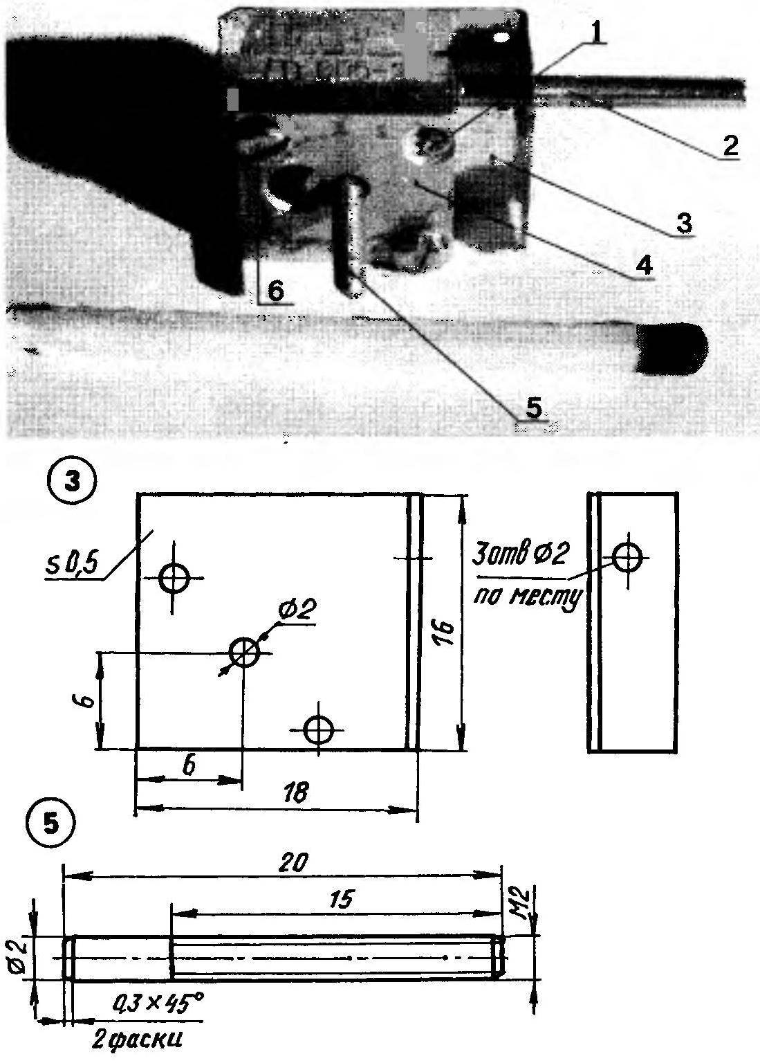
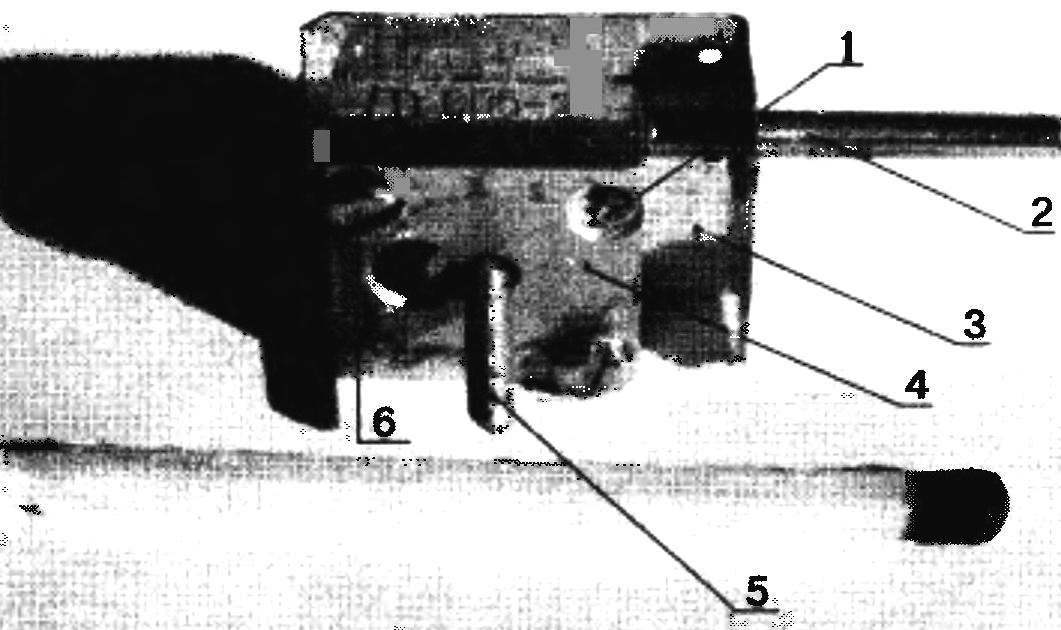
Miniature reducer:
1 — lock pin worm shaft; 2 — extension cord (tube 2×0,2 needle medicine dropper); 3 — cover (galvanized sheet 50,5); 4 — the case (from resistor C5-2); 5 — output shaft (rod Ø2); 6 — screw M2 (2 PCs.) The match is given for scale
The most difficult to produce detail — cover. The difficulty lay in the fact that it is necessary to accurately drill the four holes with a diameter of 2 mm: two for the mounting screws, and two under the output and input shafts. To achieve the required accuracy of the location of the holes in the lid (which is required to obtain high-quality gear worm gear) helped the technology of sequential Assembly and layout of the place. To do this:
– cut out of tinplate 0,5 mm thick solid billet, produced the markup in the drawing and drilled a hole with a diameter of 2 mm for the output shaft;
– gently pressed the smooth end of the output shaft in the worm gear, ensuring that they are mutually perpendicular, and inserted in the drilled a hole in the lid;
– put the housing on the threaded end of the output shaft and aligned along the contour of the cover;
– cylindrical 2-mm socket through the holes in the body turns marked, and then drilled a diagonal hole and secured the cover screws M2;
– marked out the line of bending of the cover at a distance of 5 mm from the building and dismantled it;
– in the grip of the markup produced by the bending and re-assembled worm wheel to the output shaft, the housing and the cover;
– marked out and drilled the hole for the worm shaft extension;
– removed the lid and produced the final Assembly, putting the worm gear pair using the shims;
– greased the gearbox, cover, and set the locking pin.
It should be noted that the above-described technology requires care and accuracy. After making something to fix in the lid is almost impossible — you’ll have to redo everything (I was able to gather gear of acceptable quality is only the second time).
But there is another method of making a cover: the holes for the input and output shafts are drilled to a diameter of 2.8—3 mm, collect gear, and then use the washers with 2-mm openings to expose the shafts, after which the washer soldered to the lid.
In short, for five or six hours, even an inexperienced Amateur can produce good gear that fits well into the control system sport models. In addition, it can be used as a Vernier in various electronic devices.
V. YUNOSHEV, Mogilev, Republic of Belarus
Recommend to read
 PNEUMOCOC IN WINTER AND SUMMER
Downhill on sleigh with mountains-a fascinating sport and a great way to relax. It is a pity that this pleasure is available only in snowy winter. Summer, spring and fall on such a... CHERNIHIV PATENTS
Children in a hurry. They are in a hurry to become adults. This children's line for the purpose of education first used, perhaps, to A. S. Makarenko. He loaded the boys a real job and...
