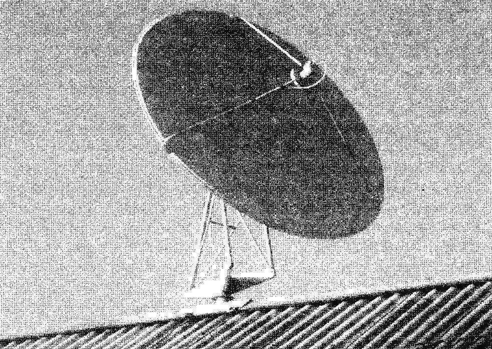
This can be done in different ways, but the most rational is to install the antenna on the roof ridge. There is no need for a complicated construction of the mast (tower). Be much easier the installation and maintenance of the antenna.
This construction in two variants presented in published sketches and drawings. The first of these is the easiest to implement and does not require high precision manufacturing parts. Its design is shown in Fig.1. The basis for the design is the mast made of steel water pipes with a diameter of 48 mm with a wall thickness of 3 mm. But mast this element can be called a stretch, as the special power loads it does not bear, and serves largely only to rotate the antenna on the transmitting satellite horizontally. To do this, at the bottom of the pipe is drilled, the radial through hole with a diameter of 10 mm under the knob.
To the upper part of the pipe is welded, three identical console with the holes on the ends for bolts for fixing the uprights of the frame of the antenna. One of the stands—telescopic, changes in the length adjustment direction of the antenna in the vertical plane. Internal fixation element is a locking screw, screw into is welded to the outer element of the nut through the hole in the wall of the element.
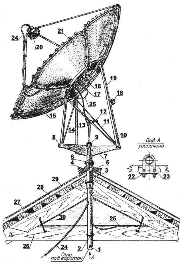
Fig. 1. The mast for mounting a satellite antenna”dish” on the roof with the possibility of manual adjustment of focus:
1 —front (steel pipe Ø48×3); 2—ladder M10 (steel, circle 10, 2); 3—bushing (steel pipe Ø56×3); 4—angled roof ridge (Board s20); 5 —angled flange for stair with the hinges (sheet s3); 6—slesnick (sheet s3); 7 console subframe (steel sheet s2); 8—fastening of racks of the frame (M10, 3). 9 plug (rubber); 10—the outer element of the strut (tube Ø26×2); 11—brace (pipe 10×1,5,2); 12—strut spacer with clamps; 13—front subframe (pipe Ø22×1,5,2); 14—rack strut; 15—reflector plate; 16—electric motor vibrator; 17—an arm of the vibrator; 18—locking screw strut; 19—an internal element of the strut (tube 22×1,5); 20—gatherer of the satellite signals; 21—light emitter (led MN-3, as required); 22—a nut M10 (2 PCs.); 23—plate (steel sheet s3); 24—antenna cable; 25—power supply cable vibrator motor; 26—bolt (Board); 27—rafter (Board); 28—crate (Gorbulina Board); 29—roof (slate); 30—clip (2 PCs.)
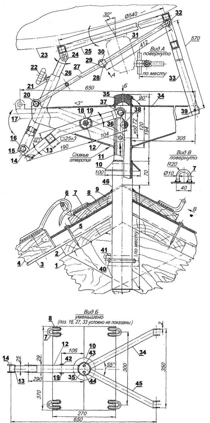
Fig. 2. The second (“advanced”) version of the mast for the installation of satellite television antennas,”plates” on the roof:
1—rafters; 2—lath; 3—slate; 4—ladder; 5—peg; 6—hook ladders (steel, Ø10); 7—loop Ø10; 8—flange (steel, sheet s2);9—skate Board; 10—canopy (steel, sheet s3); 11—front (tube Ø48×3); 12,34,45 console (steel, sheet 2); 13—rocking chair in the lowest position; 14—plug; 15,19,20,24,32,37—special bolt (axis); 16,26—strut; 17—rocking chair in the highest position; 18—Bush; 21 —welded M8 nut; 22—locking screw M8; 23—reflector antenna; 25—subframe-ring antenna; 27—brace (2 PCs.); 28—nut M6; 29 clamp spacers; 30—bolt M6; 31—vibrator; 33—front (2 PCs); 35 — upper plug (rubber); 36 — thrust (steel, pipe Ø22×2,5); 38 — plug a technological hole (rubber); 39—болтМ8; 40—ladder M10 (steel Ø10,2); 41 —plank (steel s3,2); 42—welded nut M8; 43 is a hole under the wire of the vibrator; 44—channel TV cable; 46—Bush
Slightly below the consoles to the mast welded slesnick made in the shape of a truncated cone of sheet steel 3 mm thick. Here, note that after installation of the mast on the roof of slesnick performs the function of the supporting rib.
Mounted the mast in the sleeve, cut from a tube with an inner diameter slightly larger than the outer diameter of the mast. The sleeve is also embedded and welded to the angled flange made of steel of 3-mm sheet, the “wings” which are folded along the ridge of the roof.
The sleeve serves as the upper bearing tube of the subframe. In addition to the flange welded on loops for which cling to the hooks of the ladder, which is necessary for maintenance of the antenna. The sleeve and the pipe sub-frame attached to the rafter and screw the bolt ladders. The cable from the antenna to the receiver is held in the hole of the upper rubber plug and can come out of special holes (drilled in the pipe wall of the subframe), and from the end.
There is need to pay special attention to paint the satellite antenna and its frame: as a rule, it is bad quality! Less than a year later the construction begins to rust.
To extend the service life of the antenna would need to build to do the following. Flare of sectors of the antenna before you take them off the mounting bolts, it is necessary to cover vodoavtomatika sealant. The approximate drying time of 40-50 minutes, which is more than Enough for the complete Assembly of the antenna reflector. Further, with the external and internal side, with a sharp knife cut off the excess sealant. Installing a reflector on a flat surface “Cup” up, paint the inside weather-resistant paint. It is advisable to apply at least two layers (fully dry each layer). The paint should be matte. Otherwise, reflected sunlight (under certain conditions) can focus on the core, and this will lead to overheating and failure. The spherical surface of the reflector frame of the antenna, a subframe, etc. reflective paint is not critical. To prevent deformation of the struts from the strong wind gusts additionally installed between the tubular spacer. Subject to all of the above recommendations, the antenna will serve its owner for many years.
Quick mounting of the antenna on the roof of the building next. The ridge of the roof penetrate the through hole with a diameter slightly more than diameter of the sleeve. Position the hole as close as possible to the rafter. Install the bushing on the tube of the subframe. The free end of the pipe introduced into the hole of the skate and allowing them to pass as long as the flange does not sit in place (skate), and the visor tube subframe on the end of the sleeve. Next. On the roof of the tube of the subframe put the plumb. Mark the bolt holes for the ladder. Drill holes and attach a pipe with a ladder. Then set: top ladder, the antenna frame Assembly with ring and last but not least—reflector antenna. Work on the ridge is possible only in calm weather, podstrahovyvayas rope.
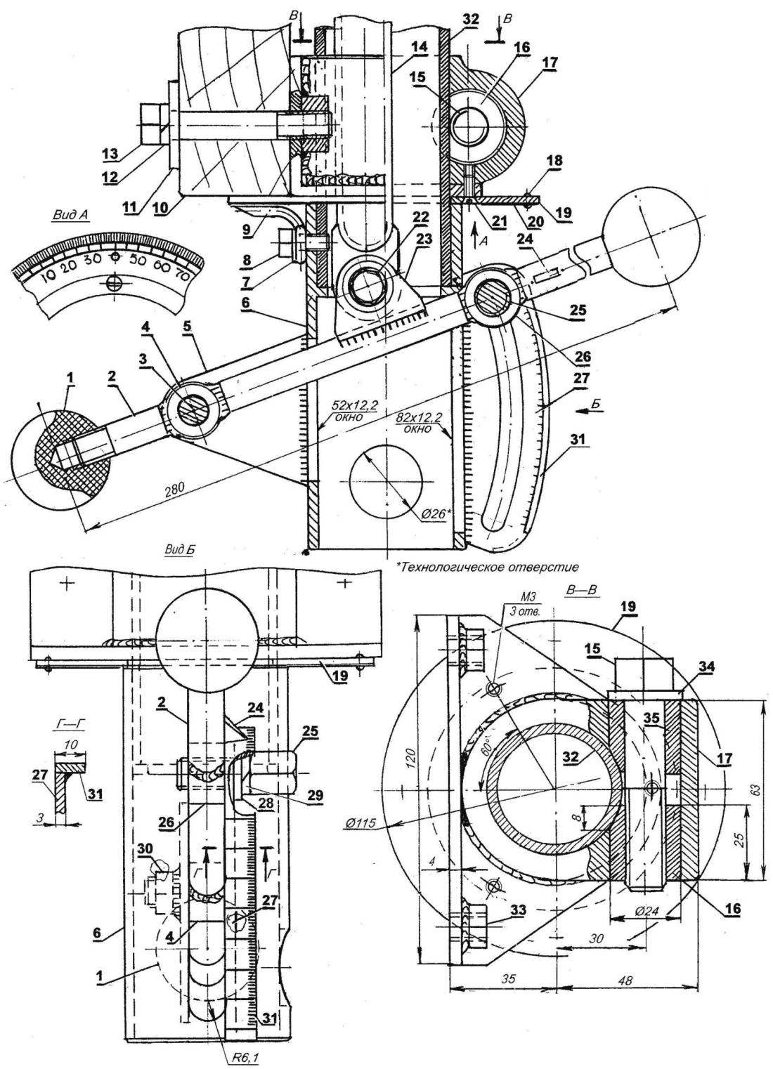
Fig. 3. The mechanism for setting the precise direction of the antenna to the satellite at the specified coordinates:
1 —ball pen (ebonite Ø35); 2—the control shaft (steel, lap 12); 3 — shaped screw M8; 4—bushing; 5—right cheek of the bracket, the left is not shown (steel, sheet s3. 2); 6—reducer sleeve (steel); 7—washer; 8—M6 screw (3 PCs); 9—arrow (steel, wire Ø3); 10—bolt; 11—plate; 12—a spring washer; 13 — M10 screw (2 pieces); 14—thrust; 15—the screw М14х1,5, 16, a wedge-nut М14х1,5; 17—bushing-bracket; 18 — rivet Ø1 (8 PCs.); 19—ring (steel s2); 20—limb horizontal orientation(metal protractor 360°); 21 —screw M3 (3 PCs.); 22 — axis (M10); 23—the plug; 24—gauge; 25 — locking screw M10x1,5; 26—threaded sleeve M10x1,5; 27—bracket (steel, sheet s3); 28 — spacer; 29 — spring washer; 30—weld-nut M10x1,5; 31—limb (cut with a scale division of 1°); 32—front subframe (pipe Ø48×3); 33—weld nut M10x1,5 (2); 34—a washer; 35—wedge-bushing
In winter (under snow) in the reflector can accumulate quite a lot of snow, which significantly weakens the signal and causes interference. Accounts as necessary to clear the antenna. Of course, this involves some inconvenience, but what can you do—as they say, should pay for everything! Sometimes a reflector is successfully freed from the snow right after the tube of the subframe several times hit with a mallet.
If the snow precipitation in this area is not so abundant, and the angle of the reflector to the horizon of not less than 50 degrees, use another successfully approved way is on a special bracket (“pin” hole) is installed an electric vibrator.
Vibrators is simple. For this purpose suitable electric motor AC or DC with a capacity of at least 150 watts at 1500 — 2000 rpm At the motor shaft is mounted with eccentric wheel, which, in turn, is locked with a screw. The mass of the wheel is chosen empirically. The vibrator is powered from a separate source. Push button electric switch (non-locking) mounted in any suitable location, with good visibility of the inner surface of the antenna for control. In some cases, to clean the reflector from the snow lasts two to three inclusions, no longer than 2-3 seconds. The longer the vibrator, may lead to the arbitrary weakening of all fasteners construction and even the destruction of some of its elements.
The reflector antenna can be provided with additional function—illumination. For this across the length of the circumference of the “plates” place (United in garlands) miniature light bulbs (type MH) or led driven color console. The effect—stunning! Is it necessary and how to implement it in practice to solve to the reader.
The second option is more complex. For those who don’t really want to climb on the roof for selective orientation of the antenna at a particular satellite. For this device the sub-frame of the antenna changes and additions. The vertical installation angle is a handle which is pivotally connected with a thrust. In turn, thrust (also hinge) is connected to the rocking chair. More shoulder rocking (again pivotally) connected to the lower end of the strut Assembly. The opposite end of the bar (swivel) connected to plug ring of the reflector antenna.
By moving the handle (up and down) ring antenna, connected by bolts with the reflector is rotated on the axis, thereby changing vertikalny^angle within 30 degrees. This is the exact orientation. But first roughly Orient the reflector telescopic stand and lock its screw. The installation of the necessary angles (horizontal and vertical) control on the limbs with a scale division of 1°.
Technological holes used for setting the axes (special bolts) prior to installation, be sure to grease with refractory greasing, however, like all other swivel joints and friction surfaces.
The locking knob is screw M10x1,5, stands subframe—wedge clamp. Of course, the manufacture of the V-clamp will have little to spend a little more time, but it was clear the work would be worth all the effort. I repeat: reliable operation of the antenna directly depends on the accuracy of the painting. So this needs to be treated with due care. This material is based on the concrete experience of installation of reception of satellite television antenna brand: WDT-C-180-II (with a mass of 22.5 kg and a diameter of the reflector 1800 mm), designed for joint operation with a satellite receiver HIC-CHIGOH (manufacturing—South Korea).
V. PETROV, S. fish, Krasnoyarsk Krai

 More rapidly advancing digital satellite TV, coming to replace the bulky radioligand lines. The population of our vast country, even in its most distant corners, appeared a real possibility of a wide choice of television channels with excellent quality of image and sound. Therefore, a great demand began to use satellite receivers with antennas in the form of “saucers.” Installation of reception of the electronic equipment does not cause trouble, but with the installation of the antenna sometimes there are difficulties: for example, in the zones of “shade” trees, high buildings, etc. In some cases, the reception of the satellite TV signal even becomes impossible. There is a need to install antennas as high as possible to get out of the “shadows.”
 THE ITALIAN “BOOM” IN SPAIN
  Dolphin learns to swim