
 Beginner ham radio production of “solid” light and music installation on the thyristors — it is difficult to implement. The scheme is simple SMU, not containing thyristors, offers the magazine “Funkamater” (GDR). The device can be connected as a mono and stereo; for that purpose, two identical input stage transistors V5, V6 (see diagram). They are connected with a three-band crossover.
Top design channel (V7, V10) passes only high frequencies defined by the small capacitance of the capacitor C12. In the collector circuit of the transistor V10 series two bulb from a pocket lantern, painted yellow.
The second channel mid — frequency. The capacitors COJ C13 determine the bandwidth dividing filter it. Lamps NZ, H4 are green in color.
The third low-frequency channel. In the filter main role is played by the capacitors C11 and C14. Lamp H5, h6 painted red.
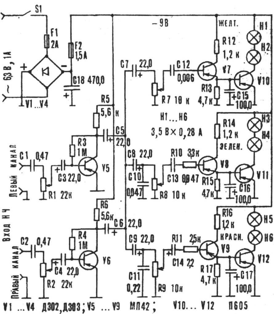
The prefix is powered from any low-power step-down transformer for the 6.3 V, 1 A Rectifier is assembled in the bridge circuit four diodes, either for КЦ402 with any alphabetic index. Termination transistors V10— V12 is designed for a current of 300 mA, for example, П605, П608, П609. The remaining transistors — low-power, low-frequency, germanium, for example, МП42—МП39. Diodes — Д302, DZOZ, Д242А, КД202А or КД208А.
Recommend to read
 THIS CAR
Maximum simplicity, minimum weight and dimensions at optimum amenities available materials, components and assemblies, simplified (not at the expense of quality) manufacturing technology... SECRETARY OF THE STUDENT
Many original equipment for studying and doing something they demonstrated this year in Moscow at the International exhibition "Technical means in educational process". Special interest...
