
 One of the problems for the citizens-owners of vehicles is the condition of the batteries. Frequent stops on subsequent runs of the engine discharged battery, a full charge from an onboard generator is at best one hour. And, as experts say, only 90 percent of waste of electric capacity is restored quickly, for some ten or fifteen minutes. The line current is reduced, and further the charge is delayed.
Relay controllers usually work in switched mode, key mode. In addition, a sharp voltage spikes due to uneven load (turn signals, brake lights) drain a battery. The charging currents are already comparable to the loss on the bulbs. That is why skeptics claim that the generator of the car sometimes can not provide the battery a full charge.
Service batteries — not heavy, but long and tedious process, and constant lack of time do not allows you to maintain a full charge. To put the batteries on charge without control is also impossible. This leads to their premature failure. When recharging oxidized grid positive plates, and they begin to crumble. The result is a reduced working surface of the plates, and their fragments can cause a short circuit in banks.
However, many of the troubles associated with batteries can be avoided if I developed to get a universal charging apparatus. Home-made, fairly compact and reliable, it allows to automatically perform the control of the training cycle (CWC) measure the actual battery capacity in CYCLIC mode, and recharge mode (STANDBY) up to par automotive ST-60 or equivalent. When bolsaescola the battery just increases the required time of operation of the apparatus, capable of providing nominal charging current 3 A, maximum 5 A, discharge current up to 7 A. operating Mode — long. Nominal power consumption mode CHARGE — 180 watts max — 250 watts. In regimes of the DISCHARGE and the ATTENDANT capacity is only 36 watts.
The device includes a control unit with charging and discharge devices and watches. The control unit monitors the voltage better than the most diligent akkumulyatorschik, — charges to the necessary level, preventing a recharge. It automatically switches from charge to discharge when reaching the limit of battery voltage (10 or 14.5 V) and also in contralaterally cycle required at least twice a year, and in the standby (precharge if the voltage drops to 12.5—13). The operator simply connect the battery and select desired mode of operation.
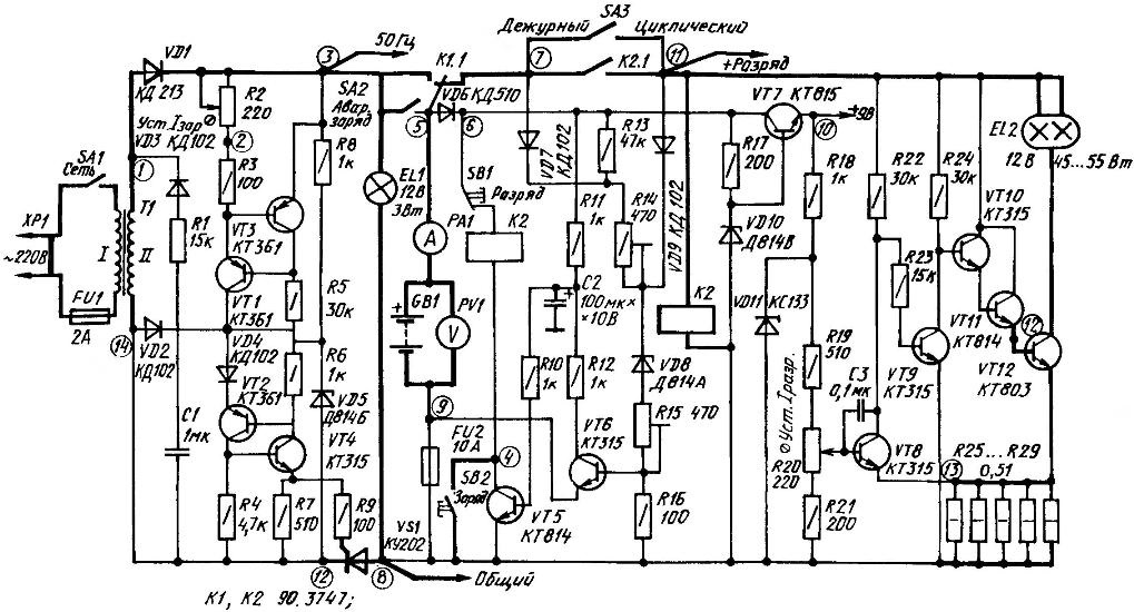
A circuit diagram of a universal apparatus for charging batteries (e-block hours is not shown)
The switch of the EMERGENCY CHARGING (SA2) include, if the terminal is less than 8 V and this voltage is not enough to trigger relay K1. While AS should be in a position ATTENDANT to the discharge device was in a disconnected state. Automatic operation is impossible, the requisite control voltage. Off the same SA2 when the 8-10 In at the battery terminals.
If relay K1 is already worked out, and the charging current does not drop to zero, switch AS to position the CYCLIC. The machine will go into automatic mode. If the current has fallen to zero, you will need to re-enable SA2 EMERGENCY CHARGE and after some time, repeat the steps outlined in the previous paragraph.
The switch SA3 determines the operation mode of the device: CYCLIC and CONVENIENCE. The first is carried out with closed contacts. With the switch SA3 in the second position, the loop will stop, but only after fully charging the battery.
During automatic operation, in other periods of the cycle is not interrupted. Already started the period of DISCHARGE is completed through the contacts of the relay K2 connected in parallel SA3. After the discharge relay K1 is switched to position CHARGE, de-energize discharge device and a relay K2. Contacts K2.1 will open.
After charging the battery, the relay K1 switches into the DISCHARGE mode, however, bit the unit is unplugged and the device goes into a state DUTY. In automatic mode, the transition from CYCLIC to standby, can last a day or more. It depends on the moment of switching DATABASES (phase cycle), the battery capacity and the established currents of charge and discharge. Relay K2 allows you to make a final or one-time measurement of the battery capacity automatically, without the need for constant monitoring of battery voltage.
The SB1 and SB2 enforce the DISCHARGE and, respectively, the CHARGE, if that is possible with the voltage at the battery. In particular, the first is fixed at a voltage less than 10 V, and the second — in excess of 14.5 V.
Voltage control allows the use of the transistor VT6, divider R13—R16, shunt diodes VD7, VD9 and Zener diode VD8. The latter increases the steepness of the switching threshold. Resistor R15 sets the lower (10-volt) threshold, and R14 — upper (14,5 V). With resistor R16 is removed, the bias voltage for VT6.
In the mode of DISCHARGE resistors R13, R14 shunted by a diode VD9. Leaking chain VD9VD8R15R16, electric current as the discharge of the battery will decrease and with it to decrease the bias voltage on R16.
Transistor VT6 remains open until voltage is 10 V (resistor R15). Closing this semiconductor opens the triode VT5, in the collector circuit of which is relay K1. Actuating, it disables the discharge device and the voltage at the anode VD9 disappears.
Earn chain R13R14VD8R15R16. Added resistors R13R14 will further reduce the current through the divider, and VT6 is fully closed.
As the battery is charging (around 14) when the voltage on the base of VT6 closer to the operating point, its negative impact will start to show the charging pulses. They will exceed the upper threshold, VT6 — to strengthen their amplitude. The transistor VT7 is closed at the time of the charging pulse, the consequence may be a contact bounce of the relay.
To prevent this undesirable phenomenon, the VT6 emitter connected directly to the negative battery terminal and not to GND. Having the amplitude to 0.7 V, the charging pulses allocated to FU2, to counteract the effects of all that stands out in R16 (0,1—0,3). Finally the capacitor C3 smooths out the ripple voltage, excluding contact bounce.
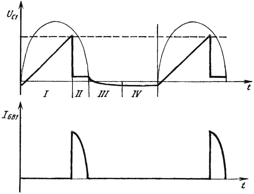
Graphs explaining the formation of a charging pulse
Upon reaching the terminal critical 14.5 V the current through the divider will increase so that the voltage across R16 will increase the release threshold of the transistor VT6. Opening, this semiconductor triode VT7 will close and shut off the relay K1. Camera switches to DISCHARGE. Resistors R13, R14 will again be bridged by a diode VD9. The current through the divider will increase significantly, VT6 opened fully, going into saturation and will remain in that state until the voltage drops to 10 V, which will lead to a repetition of the cycle.
Diode VD7 works only in a mode on DUTY and only R13 shunts, increasing the lower threshold to 12.5—13 V. the Specified parameter is not regulated and depends on the variation of the voltage stabilizing VD8. To the battery be connected to only the control unit and the clock. The current consumption does not exceed 60 mA, but it is enough to monitor the voltage.
If the voltage drops to 12.5—13 In mode CHARGE. For a few minutes (depending on the set values of the charging current, the type and condition of battery) terminal voltage reaches 14.5 V, then only the control unit is again allowed to control the voltage reduction. Such preventive charging allows for one or two years to extend the battery life.
The charger is a half-wave valve thyristor power control. Rectified AC voltage of 17.5 In the diode VD2. VT1 and VT2 transistors with resistors R2, R3, R5 form an adjustable current regulator for charging C1. Of the value of ICT set by the resistor R2, determines the steepness of rise of the sawtooth voltage on this capacitor.
The charge to the threshold key (VT2, VT4), C1 is discharged. And simultaneously energized by a control pulse to the thyristor. For the remainder of the positive half-wave will be the battery.
And now more.
In the current regulator mode is set R2R3 chain, the voltage of which is maintained at 0.6 V When IOUT is suddenly bigger, VT3 is opened, reducing the base current of VT2. And that, in turn, reduces the current through the chain R2R3. And Vice versa: the rotation of the engine, the variable resistor R2 changes the current flowing through the stabilizer. The less resistance, the more current.
Elements of VT2, VT4, VD4, VD5, R4 and R7 — R9 constitute a key threshold. The voltage at the base of VT2 is set by a Zener diode VD5, VT4 is closed, and yet has no effect. And in the beginning of a positive half-wave voltage on the emitter VT2 does not become smaller than at its base, which is unacceptable, the emitter transition in this period of time protected by the diode VD4.
As the charging of the capacitor C1 (the phase I upper graph), the potential of the emitter also increases, falling 0.6 V due to the diode VD4. Reaching the threshold, that is, when the voltage at the emitter to 0.5 V above the base voltage, VT2 will begin to open. The current flowing through it unlocks VT4. Opening up the lowers, in turn, the voltage on the base of VT2, increasing the bias voltage. Both avalanche transistor go into saturation mode. While VT2 discharges the capacitor C1, and delivers the VT4 gate trigger pulse VS1. The thyristor opens and during the remainder of the positive half-battery is fed charging pulses (bottom graph).
Chain VD2R1VT3 provides a safe setting to zero the charging current of the battery. In each negative half-cycle it discharges the capacitor C1.
In other words, if the charging current is named capacitor is too small, the voltage across it by the end of the positive half cycle reaches the threshold for opening the key (even by 0.1—0.2 In) and that will not open, and the capacitor C1 will remain charged. Key works at the beginning of the next positive half cycle. Instead of reducing the charge current will abruptly increase, threatening to reach the pulse excessively large values. Therefore, in the negative half of the capacitor is discharged through R1 and VD3 to voltage — 0.6 V (part III upper graph). Then have diode VD1, recording this voltage. The current passes along the chain VD1R2VD3 (part IV upper graph).
With the beginning of the next positive period of the same processes are repeated.
EL1 automotive light bulb (3W, 12V) discharges the battery between charge pulses, providing alternating asymmetric current charge the battery. Moreover, this method allows you to quickly remove already starting sulfation of the plates, raising the density of the electrolyte to the initial (as when filling). And it also helps to extend battery life.
Bit the device is a current regulator. Specifies the chain R19R20R21 through VD11 is supplied from a voltage source 9, is intended for hours. This dual stabilisation ensures accurate retention of the established discharge current. Base VT8 connects to the engine, the variable resistor R20 in the chain. The voltage taken from the “shells” is a guide and reference.
A current sensor are connected in parallel R25—R29. Small resistance, large power dissipation ensure minimal temperature drift. The voltage taken from R25—R29 is supplied to the emitter VT8. The capacitor C3 is connected between the base and the collector VT8, prevents the self-excitation current regulator. Semiconductor triode VT9 will agree on the phase control transistor VT8 and the cascade VT10—VT12. In the collector circuit of the output transistor is EL2 — automobile headlights 90-100W (joint lamp “far” and “near” light or twin, with one burned-out filament).
The use of such a load is much easier to work VT12 at high currents. The maximum power dissipated in the output transistor 4 falls on A and is 50 watts. With further increase in voltage, and hence power dissipation on the collector VT12 falls and EL2 begins to Shine brighter. The voltage of such a load is not raised above 10, so the spotlight will last a long time.
When battery power is reduced RAZR. As a consequence, the voltage on the sensor (R25—R29) decreases, the transistor is opened VT8 and VT9, on the contrary, is locked, increasing the capacities of the VT10. Transistors VT10—VT12 are opened, restoring the set value of current.
Such a rigid stabilization of the discharge current allows you to easily calculate the capacity of a given battery load. This is a simple one only arithmetic operations — multiplication (set current x the discharge time). Direct reading required here the second factor is controlled by the electronic clock. Not necessarily (but preferably) built in; the construction is convenient and reliable timepiece will be considered later.
S. KHRISTOFOROV, Yoshkar-Ola
(To be continued)
Recommend to read
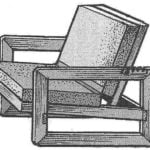 CHAIR COMFORT
It will look good not only in the countryside but in a city apartment, featuring special convenience and originality of design (in addition, it is available for self-production). The... Diagnostic voltmeter
The operating life of lead acid batteries largely depends on their proper operation. According to technical conditions, it is unacceptable to discharge one section below 1.7-1.8 V....
