
 “What to replace the gauge?” — this question often arose during the meeting with an interesting measurement scheme. Ohmmeter, voltmeter, test transistors — these devices are difficult to imagine without a milliammeter. Nevertheless, this instrumentation can work without a dial indicator. This is easy to see, collecting scheme, in which the role of the indicator does… sound generator.
Our first instrument — a probe. Without him, it is difficult to establish even the most simple electronic circuit: to check the correct connection details, and reliability of rations, the lack of breaks in the windings of transformers, chokes, inductors. The probe allows not only to identify errors in installation, but also to find the faulty part. Diagram of the device shown in figure 1. In the collector circuit of low-power low-frequency transistor T1 includes winding of the transformer TR1. Its secondary winding connected to the base of the transistor. When the test probes touch each other (or connected to the circuit with a small resistance), to the base of transistor T1 through resistor R1 is supplied a negative voltage. On account of the strong positive feedback between the collector and base circuits is generated (excitation), and in loudspeaker the sound comes. The pitch of the sound depends on the capacity of the capacitor C1, the resistance of the resistor R1 and check the plot diagram. Thus, by changing the pitch of the sound it is easy to judge the comparative value of resistance of certain fields “prozvanivatsya” chain. Source tone select to change the resistance of the resistor R1 (the resistance increases as the pitch increases) or the capacitance of the capacitor C1 (increasing the capacity reduces the pitch of the sound).
In the scheme of a probe you can apply a homemade transformer, wound on a core cross section of 1.5 cm2. The primary winding has 1000 turns of wire of PEL 0,1, secondary is 60 turns of PEL of 0.4. Fit and ready transformers, for example, from speaker loudspeaker Iskra (15 In) or output transformers from transistor radios with push-pull output (high-resistance winding is in this case fully included in the collector circuit). Loudspeaker Гр1 — type 0,1 GD-3, GD 0,1-6.
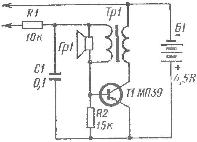
Fig. 1. Schematic diagram of the probe:
resistors R1, R2 — VS-0.25, MLT-0,25; capacitor C1 — MBM.
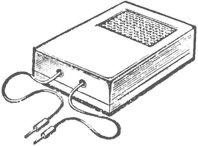
Fig. 2. The appearance of the probe.
Power source — battery 3336L (KBS-L-0.5) or three element 332 (1,3 FMC-0,25) connected in series. Under open-loop probes, the transistor is closed and current from the source practically does not consume.
A diagram of the probe mount in the housing pocket radio (Fig. 2) or in some other appropriate case.
When building circuits it is important to know the gain of the transistors. An indispensable tester of transistors (Fig. 3) — the instrument for testing low power semiconductor transistors of different conductivity. The measurement range is from 10 to 100. It is easy to expand in a big way, but do not do this, because the transistors with a gain of more than 100 whimsical work, and we do not suggest to use them in your homemade.
Using the switch changing the polarity of the inclusion of the battery B1. It depends on the type of conduction check of a transistor. So, in the top (the scheme) switch position check the transistors with p-n-p conductivity: in the collector circuit of the transistor is fed “minus”, and on the emitter — plus power supply.
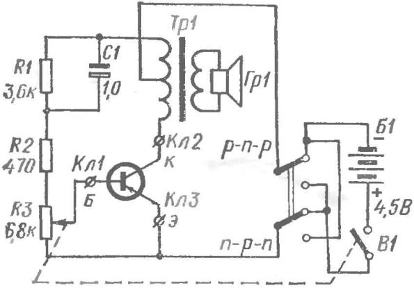
Fig. 3. Schematic diagram of test transistors:
resistors R1, R2 — VS-0,25, MLT-0,25; electrolytic capacitor C1—K50-3, K50-6.
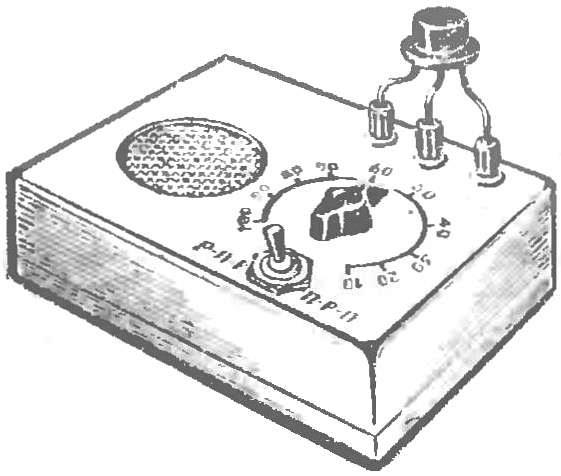
Fig. 4. The appearance of the test transistors.
Once the terminals “K”, “B” and “e” connected transistor, the circuit becomes a generator of alternating voltage. Dragging the slider of the potentiometer R3 to the top (the scheme) position, to achieve the excitation of the cascade, and the emergence of sound in the loudspeaker Гр1. It is clear that the greater the angle will be rotated the potentiometer, the smaller the gain is the transistor. The gain values read on the handle position of the potentiometer R3.
Resistor R1 limits the maximum collector current of the transistor, and the resistor R2 affects the lower limit of the range of operation of the device.
Potentiometer R3 can be any type (preferably paired with a power switch). TP1 — output push-pull transformer from a pocket transistor radio. Loudspeaker Гр1 — type 0,1 GD-3, GD 0,1-6.
Details of the scheme put in improvised housing (Fig. 4) with a removable bottom cap. On the front panel of the case reinforce the speaker, potentiometer, terminal and type switch transistors.
To calibrate the device, you will need a few transistors, the gain of which is known. The transistors in turn are connected to terminals “a”, “B”, “K” and rotate the potentiometer R3, to achieve the appearance of generation. The gain values are placed on a scale.
The last of a series of “singing” instruments — voltmeter (Fig. 5). It allows to measure DC voltage in the range from 0.2 to 1000 V. For convenience, the whole range is divided into five sub-bands: 0.2—2 V, 1 — 10 V, 5-50 V, 25— 250 In 100 To 1000 V. Each sub-band has its own terminal. To control the voltage of the power supply has an additional terminal. Enough to connect its probe to the terminal “1-10”, and on the scale of the voltmeter to determine the voltage of the battery B1.
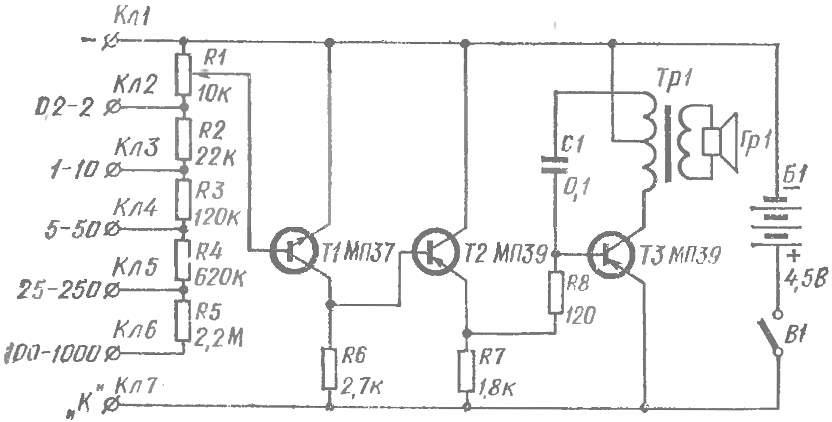
Fig. 5. Schematic diagram of the voltmeter:
resistors R2 — R8 — VS 0,25, MLT-0,25; capacitor C1 — MBM.
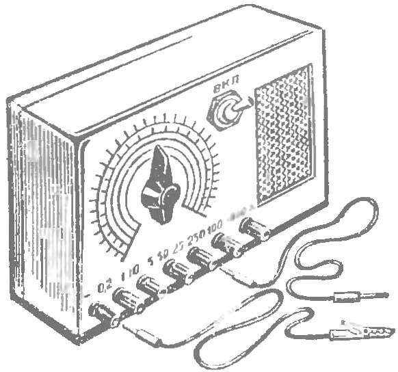
Fig. 6. The appearance of a voltmeter.
The main part of the circuit voltmeter — generator, assembled on the transistor T3. In the collector circuit of the transistor is included the primary winding of the transformer TR1 with tap from mid point. The feedback voltage is fed through capacitor C1 to the base of transistor T3.
The measured voltage is applied to the divider made up of resistors (R2 — R5 and potentiometer R1. With the potentiometer voltage in the proper ratio is supplied to the base of transistor T1 is reverse conduction. To increase the input resistance of the voltmeter between the amplifier stage and the generator is included the emitter-follower transistor T2. Moving the potentiometer R1 down (on diagram), we thus increasing the negative voltage at the resistor R7 and base of transistor T3. At a certain voltage, the transistor will open, and there is generation. If the engine is to continue to move generation again disappears. The readout voltage is produced on the scale, fortified against the handle of the potentiometer.
A variable resistor can be of any type, with the resistance 6,8 — 10 kω (preferably a linear feature). Transformer TR1 and the loudspeaker Гр1 — from a pocket radio. As a T1 you can use the transistors P10, P11, МП37, MP38 gain of 15-30. The transistors T2, T3 — МП39—МП42 ratio gain 40-80.
The design of the voltmeter shown in figure 6. On the front panel fasten the loudspeaker, a potentiometer, terminals, circuit breaker. On the axis of the potentiometer slide knob with the arrow and proceed to the calibration of the scales.
Control connect voltmeter across the terminals of your device. Feeding different voltages, mark the scale position of the knob of the potentiometer, corresponding to the time occurrence of generation. Each time the knob should start to rotate from the leftmost position: when the approach
A value of the measured voltage (the beginning you will hear a faint high pitch sound that further rotation of the handle disappears and instead there is a loud low-pitched sound.
The stability of the voltmeter depends on the voltage of the power supply. Periodically check and in time to change the battery!
IVANOV
Recommend to read
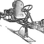 SNOW GO-KART
It's easiest to say: "When I grow up, I'll get behind the wheel of a car, take a plane into the sky, build what I dreamed of..." But it turns out that many dreams can come true even at...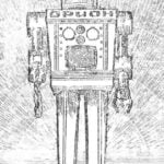 MEET: I — ROBOT “ORION”
Perhaps in the near future when the new spacecraft will go to the moon, Venus or Mars in the Arsenal of the astronauts will be robots who will come first to the planet's surface to...
