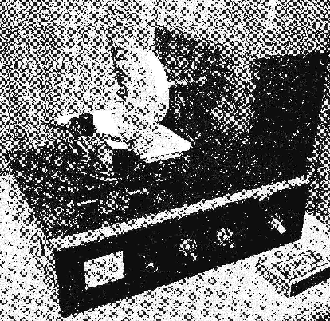
 When performing electrical work have to drill a very large number of holes in the walls and partitions. In a brick or prefabricated houses not to dispense with carbide drills. However, such a tool is not enough for a long time: the working edges of the drill bits become dull and crumble and need to be sharpened. This is typically done using special “green” wheels, but they are expensive and wear out quickly. Faced with this problem, I started looking for alternative technology and stopped at electroerosion grinding devices.
In developing the proposed readers electroerosion grinding device (EXU) has provided in him also the ability to connect and adjust string Thermaltake for polystyrene, plastic, etc.
In the sale of devices using electroerosion, was not (and even if it was, it is not known how many would have had to pay), so I decided to make myself “of what was”.
Their essence consists in the following. When closing or opening of the conductor at a certain point the gap between the approaching contacts becomes so small that between them a spark. The temperature in the zone of the spark increases dramatically by several orders of magnitude, which leads to thermal damage of contiguous elements.
For switches, circuit breakers, relays, etc electroerosive — an undesirable phenomenon, which eventually leads to their failure and need replacement. But bad for contacts of switching devices, electroerosive been found useful for electro-spark method of processing metal parts. For example, this technology through the shaped working electrode to obtain a matrix of complex configuration. With no less success electroerosive can be applied for grinding of various tools, including carbide drills.
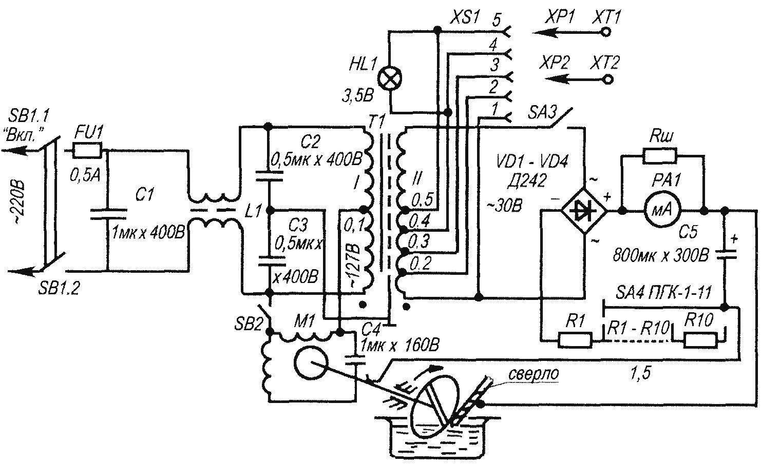
Fig. 1. Electrical schematic electroerosion grinding device
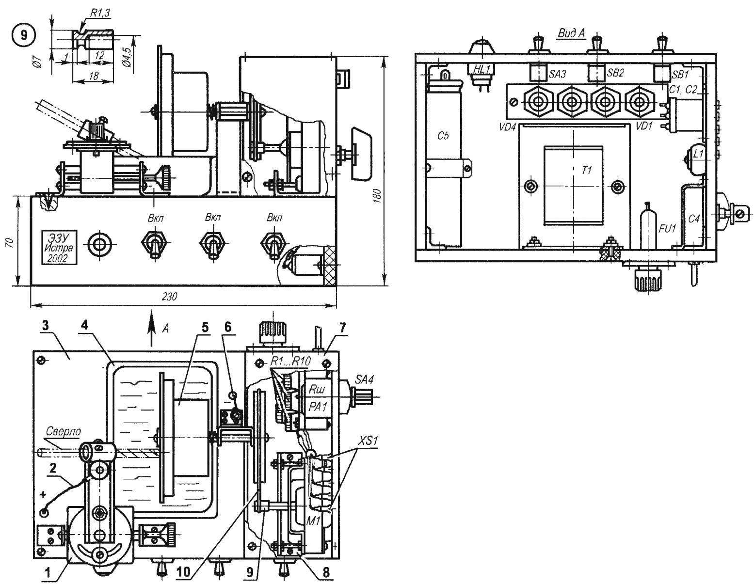
Fig. 2. Electroerrosion sharpener:
1 — support; 2 — positive; 3 — base; 4 — cuvette with water; 5 — drive unit of the working electrode; 6 — negative pole; 7 — casing (galvanized sheet s0,7); 8 — bracket motor M1 (AMT-6, area 20×20); 9 — drive pulley; 10 — “belt” (pencil with rubber)
Functionally it consists of the following components: filter, protect your network from interference (C1, L1, C2, C3); power transformer T1; elektrodvigatel M1; rectifier bridge VD1 — VD4 with a charging capacitor C5; the indicator PA1 operating current; the step of the current regulator ЅА4 with R1 — R10; cells filled with working fluid — water (the cuvette used an empty pack of processed cheese).
All nodes in the EXU (Fig.2) are mounted on a base made of 8 mm plywood, lined with plastic to protect it from possible moisture. The base part are connected together using angles and bolts. On top of the base using the bracket mounted electric motor M1 “belt” transmission (belt — stationery eraser), a closed casing of galvanized sheet. On the rear wall of the casing is provided with indicator operating current PA1, switch speed adjustment ЅА4 with the resistors R1 — R10 and an insulating plate with the sockets ХЅ1 to power a string of termosesov.
In the centre of the base on a support consisting of uprights and brackets, mounted the drive unit of the working electrode. Right on the shaft (the rod with a diameter of 6 mm) using a 1 mm pin with screw M3 mounted driven pulley of the belt transmission. And on the left end of the shaft similarly mounted electrode on the faceplate, which is used podcatching from the old tape recorder “Mayak”. (If you have this item manufactured again, its form can be simplified to a flat disc.) To prevent movement of the Chuck on the shaft, 14 mm from its left end face is a flange (it can be machined by turning or if it is difficult to solder to the 6-mm rods a suitable washer). Between the flange and the bracket supports in the cups located compression spring to prevent axial play (cups and spring from the rear brake pads “Lada”), It is necessary to ensure a stable gap between the electrode and the drill bit during sharpening. Under the spinning electrode mounted cuvette with water, which lowered the sharpened core drill bit embodied in the clamp of the caliper. The caliper is designed for smooth supplying of the cutting edge of the drill at a certain angle to the circulating electrode.
Inside the base includes a power transformer T1, a filter protection from interference network (C1, L1, C2, C3), strap a diode bridge VD1 — VD4 and charging capacitor C5. On the front wall of the base installed the switches SB1, SB2, SA3 and lamp signal HL1.
The inductor L1 of the filter network protection from interference is made on a ferrite ring НМ1500 20x12x6 winding of two wire mgshv-0.12 and has 30 turns. Capacitors C1, C2, C3 — type MBGO.
The transformer T1 is made on the core Ш30х31. Winding I start to withdrawal is 0.1 635 turns of wire sew to 0.33; 0.1 to the end — 465 turns of PEV 0,31. On-screen winding made of aluminum foil 0.1 mm thick and has a 1.5 revolution.
Winding II from the beginning to the removal of 0.2 has a 2.5 coil, drainage from 0.2 to 0.3 — 5 turns from dissipation of 0.3 to 0.4 — 10 turns from dissipation of 0.4 to 0.5 — 20 turns of wire sew a 1.5. 0,5 from the elbow to the end 112 of turns of PEV 0,8. Between the winding layers of padded liners from polietilentereftalatnoy film with a thickness of 0.06 mm in a single layer, between the windings in two layers. The motor M1 type ЭДГ1-1 from the old player. It is powered by a withdrawal of 0.1 winding I of the transformer T1 (the voltage — 127).
As used SB1 switch TP1-2, and as SB2 and SA3 — toggle TV2. The diode bridge VD1 — VD4 can be performed on the diodes Д242, Д215, D305 or similar, calculated on the current 5 — 10 a Diode bridge mounted on aluminum plate size 110x25x5 mm and insulated from it by washers of mica with a thickness of 0.1 mm.
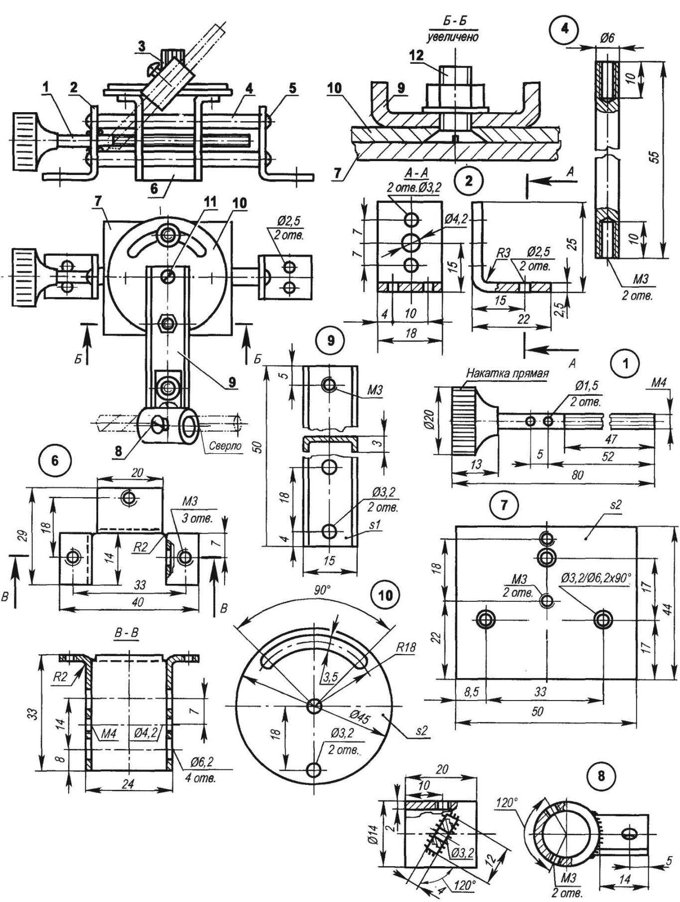
Fig. 3. Stand:
1 — screw; 2 — bearing (steel, strip 18×2,5,2); 3 —notched nut (M3, radio); 4 — track (steel, rod O6, 2 items); 5 — mount rails (screw M3,4 PCs.); 6 — carriage (steel, sheet s1,2); 7 — (steel, sheet s2); 8 — clamp; 9 — yoke bracket (steel, sheet s1); 10 — washer (steel, sheet s2); 11 — axis washers (screw M3); 12 — mounting bracket clamp (screw, nut M3)
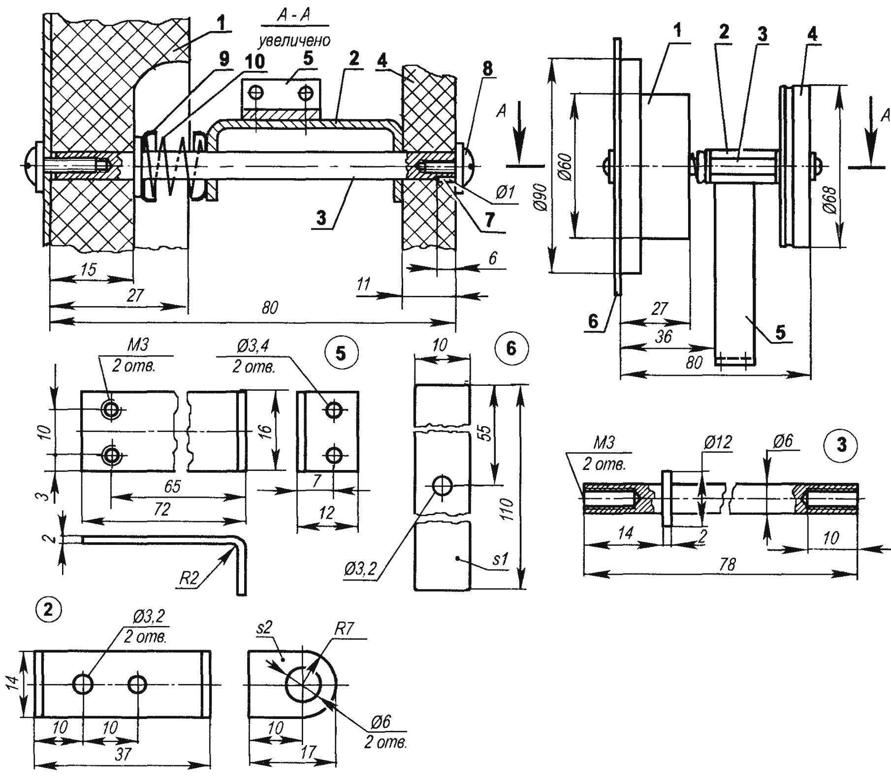
Fig. 4. The drive unit of the working electrode:
1 — faceplate (podcatching from tape recorder “beacon”); 2 — clip (steel, strip 14×2); 3 — shaft (steel, circle 6 or 12); 4 — clutch pulley belt transmission (from tape recorder “Mayak”); 5 — (steel strip 16×2); 6 — electrode (copper, brass, steel, sheet s1); 7 — pin (steel wire O1,2 PCs.); 8 — M3 screw (2 pieces); 9 — Cup(2pcs.); 10 — compression spring (from the rear brake pads “Lada”)
For the current indicator PA1 device is used М476, the resistance of the frame — 550 Ohm, she was taken from old reel to reel tape of the “lighthouse”. Rш resistor made of nichrome wire with a diameter of 0.6 mm in two leads, and when the above resistance frame length of the conductors was about 40 mm. Rш chosen so that when current is 2A needle was between blue and red sectors. As the speed of the current controller used switch SA4 PGK-1-11 eleven provisions. From the variable resistor or rheostat had to be abandoned due to strong heating of the movable contact Resistors R1 — R10 are made of nichrome wire with a diameter of 0.6 mm. They are frameless and are wound on a mandrel 5 mm in diameter. Resistors soldered on the switch contacts ЅА4. Charging capacitor C5 — oxide pulse brand К50И-8. It would be possible to use a capacitor and easier (for example, K50-6, 1000×50 In), but it is less reliable and not as durable than a pulse.
Work on EXU
If you want to work with a string Thermaltake, the switch SV1 network must be enabled, and the switches SV2 and AS — disabled. Rearranging the plugs ХР1 and XP2 in the nests ХЅ1 (1 — 5), select the position in which the contacts ХТ1, ХТ2 will be obtained the voltage required for work of Thermaltake string.
When sharpening drills ЅА4 switch is placed in the rightmost position. The drill bit is installed in the retaining clip caliper and pre-fixed there by two screws, and then use the rotary table of the caliper is supplied to the rotating electrode while the rotating tool into the clamp of the caliper is set to the angle of its trailing edge. Further, the drill bit is finally fixed with two screws clamping the clamp of the caliper. By rotating the handle of the screw of the caliper end of the ground auger is supplied to the plate of the rotating electrode to a light touch. Turn on the switches SV2 and SA3, starts the motor M1 and to rotate the electrode. It is necessary to achieve sustainable arcing ground end of the drill and the rotating electrode by using the lead screw of the caliper.
Then in the cuvette was filled with water so that the touch of the drill and the electrode was immersed in water. Need distilled water or rainwater. Switch ЅА4 set the operating current of the indicator PA1; the arrow should be between the blue and red sectors, which corresponds to a current of about 2A.
When working EXU between the drill bit and rotating electrode a spark is sharpening. Upon termination of the sparking end of the drill again with the help of a lead screw of the caliper is supplied to the rotating electrode. After sharpening one edge of the drill bit is rotated in the mounting bracket clamp and sharpen the second edge. The rotating electrode is in the water under the tap with a drill a short time, so the decomposition of water is almost negligible. Work on EXU is not accompanied by dust emission, as in conventional grinding devices.
Technical characteristics EXU
The speed of rotation of the working electrode, rpm…..140
Time sharpening drill bits, min:
with a diameter of 6 mm…………………………………………………..3
with a diameter of 8 mm…………………………………………………..4,5
with a diameter of 10 mm…………………………………………………5,5
Sharpening angle, deg……………………………………………….120
The voltage Thermaltake, ……………………from 0.5 to 7.5
increments of 0.5
The current consumption of a working electrode, And 2…
Power consumption EXU, W…………………………60 — 70
L. STEPANOV
Recommend to read
 TRACTOR “WORLD ON A STRING”
To make myself a mini-tractor (MT) is a dream of many. But they sometimes stop because of the difficulties in acquiring scarce nowadays powertrains, gearboxes with the right gear... RAPID SNOW RAID
SNOWMOBILE RF-8-GAZ-98. Snowy and cold winter of 1941/42 created the conditions for widespread use we combat and transport equipment. "Hint" the Russian winter has been perceived by our...
