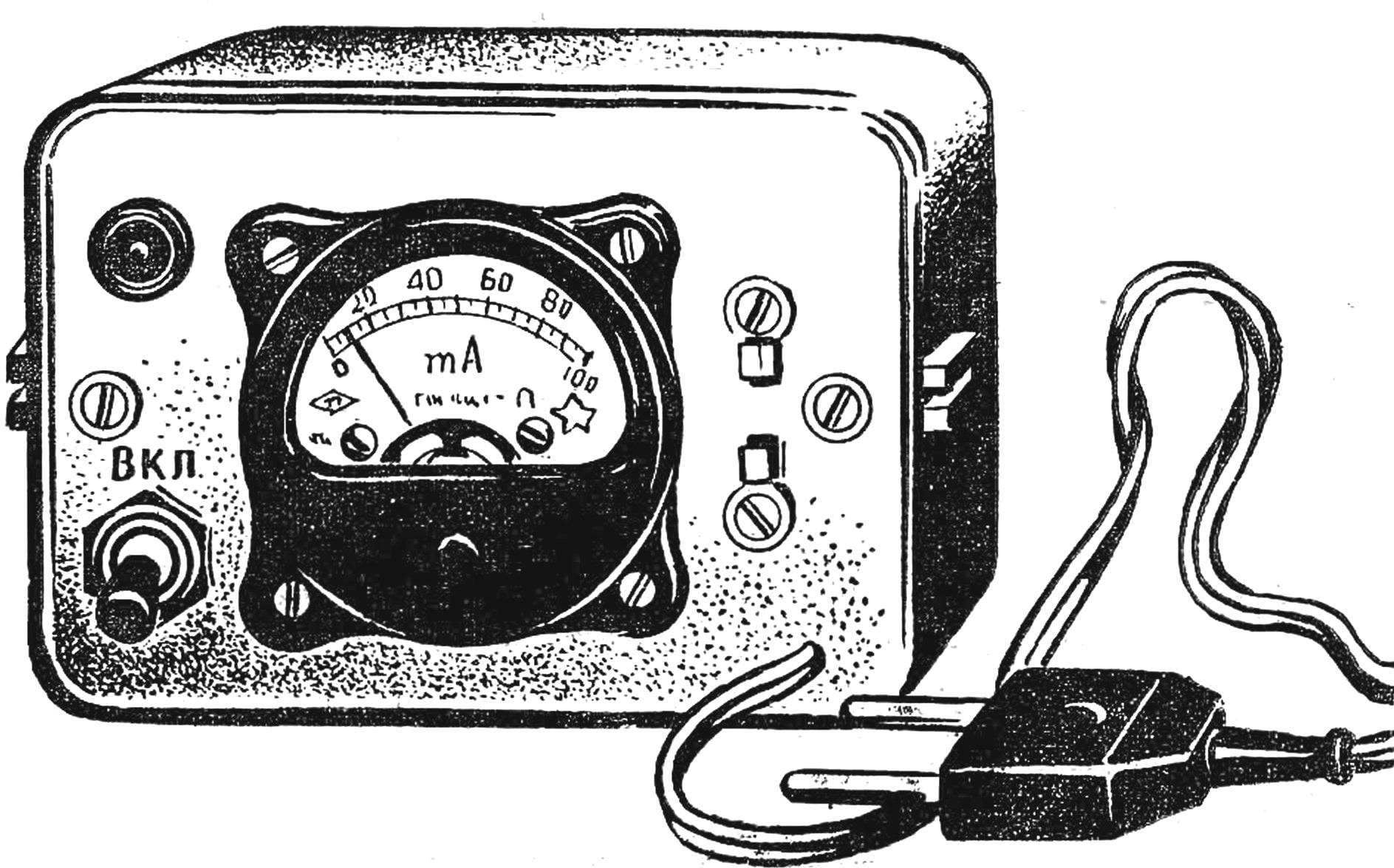
 allows you to quickly verify the health of the quartz resonators. Diagram of the device consists of a generator (T1), detector (D1, D2) and DC amplifier (T2). By connecting the quartz to the two terminals of the generator, the power on. If the resonator is OK, resistor R2 appears to the high-frequency voltage which is then fed to diodes D1, D2 for detection. Highlighted in this case a constant component opens the transistor amplifier stage. Load UPT serve milliammeter ИП1 and lamp L1. The glow lamp indicates the functionality of the quartz. But his activity is judged by the readings of the milliammeter. For the active resonator current is 70-90 mA, and for inactive — 30-40 mA.
Test quartzes can be powered from the battery voltage 9-12 V, which is connected instead of the rectifier.
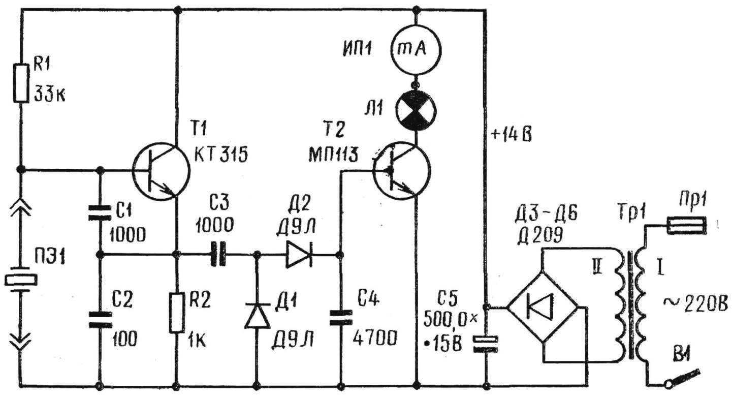
Schematic diagram of the test quartzes.
Data details are given of the PA scheme. Capacitors C1, C3, C4 — CBC, C2 — CTC, C5 — C50-6. Milliammeter type M5-2 with the current full deflection of 100 mA. As Tr 1 used television unified the transformer TCE-70. L1 — switch lamp 12 ВХ60 mA.
G. VEREIN, Ordzhonikidze
Recommend to read
 SAILING… WIND GENERATOR
They say that the new is the well forgotten old. And energy seems to be no exception here. Having burned itself at Chernobyl and faced the threat of an energy crisis in a number of places,...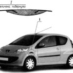 REPAIR IT YOURSELF!
A small speck of rust on the wing in a few weeks darkened, and then turned into a hole with ragged edges. Avtostantsii the sentence was harsh - the wing needs to be changed. Preliminary...
