
 The weight started with the fact that the employee of the bell States telephone laboratories in new Jersey (USA) D. Hagelbarger created in the early 50-ies of the cybernetic device to play the so-called “coin”.
The essence of the action of the machine was the fact that playing with a man, he “remembers” their moves and the moves of the man in previous games, as well as the results of these parties. Analyzing the information it has discovered a strategy that consciously or unconsciously, adhered to the enemy, and, given the CoE, have scored one victory after another. For several weeks the staff and visitors of laboratories have played with a cyber partner. From 9795 parties machine won 5218.
Machine Hagelbarger interested in Claude Shannon, a world — renowned expert in the field of Cybernetics. On the basis of the same principles he created his own machine to play in “dime” — more simple and with less memory.
After much debate, which “talented”, it was decided to perform an experiment. Constructed the third device-the intermediary, which could transmit information from one machine to another, to count points and make sure that the game was played according to the rules. Three machine connected to each other and installed in the auditorium of the same bell States telephone laboratories. Machines started the game. The audience applauded good moves machines, they made a bet, “rooting” for the elect, as in a real competition. Machines played a few hours. Right was Claude Shannon: his “less intelligent” machine won with a score of 55 to 45.
Using the idea of “intelligent” machine-player, we created a model that is available for manufacturing in the school engineering club.
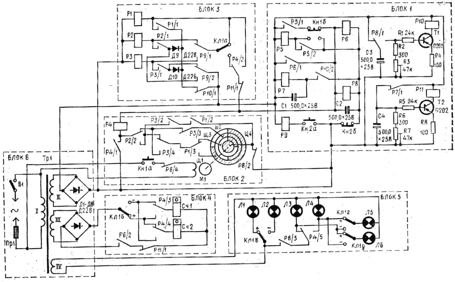
Fig. 1. Schematic diagram of the gaming machine.
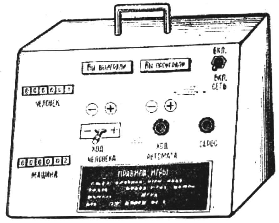
Fig. 2. The front panel of the machine.
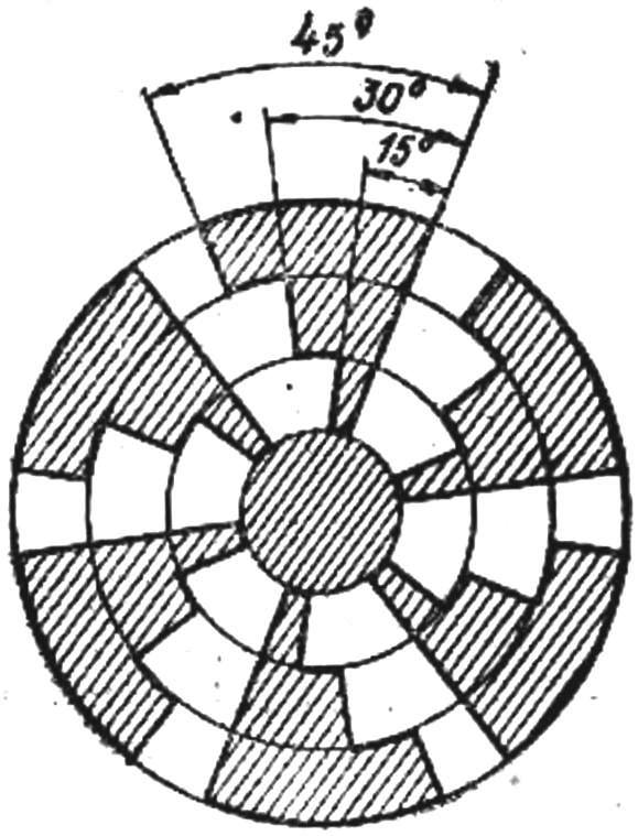
Fig. 3. Disk with a conductive sectors.
A schematic diagram of implementing the strategy of the machine (Fig. 1) consists of blocks of control, choice, memory, display, power. On the front panel (Fig. 2) is the handle of the key (KL1) “move person” button (KN1) “move machine” button (Кн2) “reset”, the counter of the winnings of a person (Сч2), the counter of the wins model (Сч1), four light bulbs, fixing of (L1, L2) and machine (LZ, L4), the light Board: “You have won” (L6) and “You lose” (L5), network switch (B1).
The rules of the game with the machine are as follows: after turning on the power model, the man, by key KL1 needs to make his move and then click on the “move machine” (KN1). When the machine at the counters will note the outcome of this game (the coincidence opaque and wins the car, in case of discrepancy — people), need pressing the “reset” button (Кн2), to prepare a model for a new party.
Consider a model with specific examples, denoting the moves as “+” and ” — “. Immediately after turning on the power relay R11: capacitor C4 is charged and the transistor T2 opens. Rasikas, contacts R11/2 eliminate premature triggering of the counters Сч1 and Сч2, and contacts R11/1 –entering information into the memory unit 3. Let’s say that the man turned the key KL1 in the position “+”. While a lit up lamp JI1. Then he pressed the button KN1: contacts Кн1а closed the power circuit of the motor M1. Fixed PA his shaft plastic disc, the surface of which is covered with copper foil, begins to rotate. The disk is pressed against the four stationary radially extending contact brushes (Щ1— Щ4). To brush Щ4 supplied voltage from the power source, the other connected to the relay R4 through a logical chain composed of relay contacts of the memory block. The surface of the disk, on which slide upon rotation of the brush Щ1, Щ2, Щ3, respectively 3/4, 1/2, 1/4 part is covered with metal foil. The time stops when the disk rotation is chosen arbitrarily: the player by clicking on the button KN1, does not see how a rotating disk. Contact “brush disc” will pass current during such stops do not always: Щ1 — in 3/4 cases Щ2 — 1/2, Щ3 — 1/4 in.
As consistently with brushes and disc included electromagnetic relay R4, it will work (as time stops disc) randomly, with probability 3/4, 1/2 or 1/4 depending on which of the brushes is connected. If the relay R4 will work, so the machine chose the “plus” doesn’t work — on the scoreboard machine will be “minus”. Copper surface: drive you need to break pas the narrow part located PA plastic disk (Fig. 3).
Simultaneous with the start engine button contacts KN1 deputies cabins supply circuit of relay R5. It resolves, and prevents its contacts R5/2. But the Kh1 button is released, relay R6 is activated (chain closes its power contacts Кн1б, P5/1 and cambiocorsa contacts R6/1), At the same time, the contacts R6/1 is connected to the power source of relay R4, R8 and the input circuit of the memory block 3. Contacts R6/2 short circuit power meters Сч1 and Сч2. In the open position, these contacts eliminate false triggering of the counters before the button is pressed KN1. Contacts P6/3 turn on the power to the bulbs L3 (“—”) or L4 (“+”) and L5 (“You lose”) or L6 (“You have won”). Contacts R6/4 are simultaneously de-energised supply circuit of the motor M1. Now, even if the player wants to change the unfavorable course of the machine, re-start the engine, he will not succeed.
The scheme of the machine is such that in the first game of the game he chooses plus or minus with probability 0.5 (contacts R2/2 and R3/3 is connected to relay R4 brush Щ2). If the car chose plus relay R4, and prevents its contacts R4/1. Contacts R4/5 include lamp L4 and displays “You lose” (L5), as the signs of man and machine match. Relay R8 is triggered with some delay relative to the relay P6: parallel relay R8 included electrolytic capacitor C2. Contacts R8/2 disable the voltage applied to the drive.
Now there is no switching in the memory block will not change the selection of a machine.
Contacts R8/1 connect the capacitor C3 is charged up to the voltage of the power source to the base circuit of transistor T1. The latter opens and the relay R10 is actuated. Contacts P10/2 connect a relay R7. bridged by a capacitor C1 to the power source. Relay P7 via a second work, and its contacts R7/1 is open. Capacitor C4 begins to discharge through the input circuit of transistor T2. As the capacitor discharge current in the base circuit will decrease. This, in turn, will cause a decrease in the collector current, and after a while relay R11 will turn off. Contacts R11/1 R11/2 completing the power supply circuit of the memory block and counters.
In our example, work counter Сч1 (KL1 in the “plus” and P4/3 in the lower position according to the diagram), counting one point in favor of the machine. In the memory unit tripped P2. registering the machine win (KL1 — in the “plus” and R4/2 in the right position according to the diagram). Relay P1 locks the choice machine plus sign. In the memory relay R1 “remembers” the progress made by the machine in the last game, and relays P2 and P3 store information about the outcome of the last two games. When winnings machine relays P2 and P3 work, when losses no. After relay R11 relay R10 is disabled. Settings time switch on the transistors T1 and T2 are selected such a way that the relay R10 worked until, until will not turn off relay R11. Exposure time adjust variable resistors R3 and R7. When relay R10 is disabled, contacts P10/2 will open the supply circuit of the relay R7. Latest your contacts R7/1 connect the “minus” supply to the input circuit of the transistor T2, which opens the relay R11 is activated.
When the button is pressed Кн2 Reset, breaks the supply circuit of relay P4, P5, P6, P8, bringing them to their original state. At the same time the relay P9. Contacts Р9Д switch power to relay R3 in the following game of the game, and contacts P9/2 provide a first locking relay P2.
In the second game of the game machine operates the same, only the choice of the plus sign is performed with a probability of 0.75 (relays P1 and P2 worked, and the logical chain is connected to relay R4 brush Щ1). This is consistent with the algorithm of the game: if the last two batches one loss and one win machine choose a recent party with a probability of 0.75, the previous party machine chose the plus sign and won, and since his memory is not the result of an earlier party, he “finds” her lost.
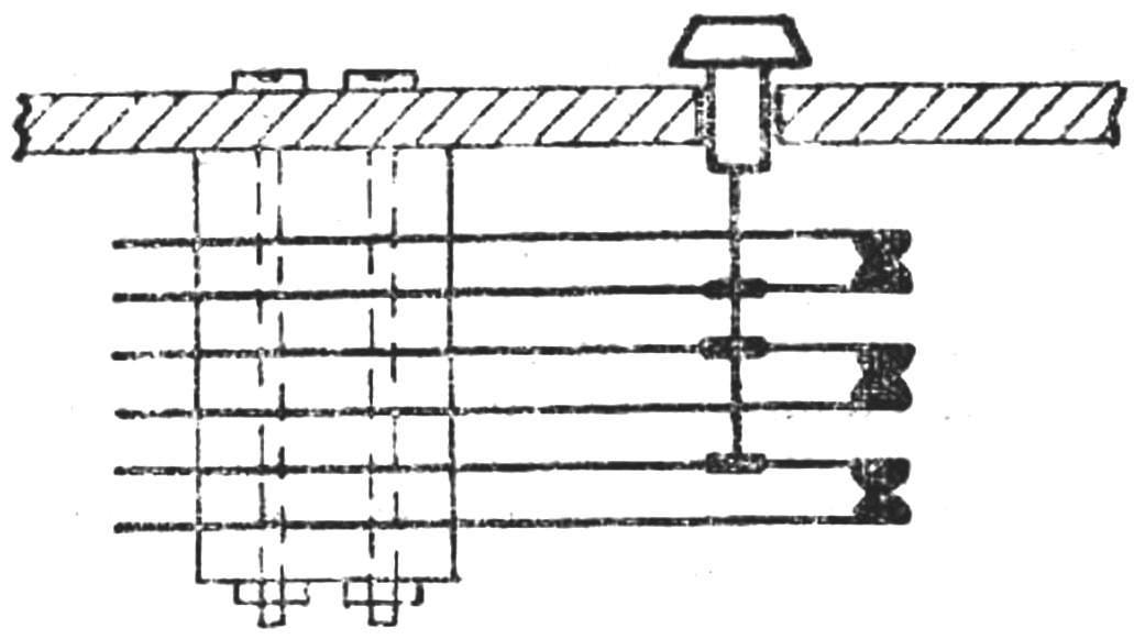
Fig. 4. Button design “Progress machine”.
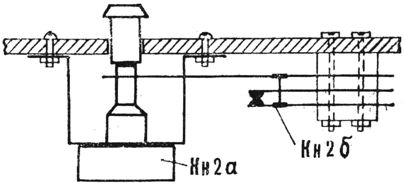
Fig. 5. The design of the “Reset”button.
Assume that both the human and the machine chose the plus sign. Lamp will light L4 (“+”) and scoreboard L5 (“You lose”). When the machine chose the second course, relay R10, and R10 contacts/1 break the chains the hold-in relay P1, P2, P3. Relay R1 is deactivated — “forgets” machine selection in the previous game and once again ready to “remember” the new choice of move made by machine in the second game. At the same time relay R2 is turned off, as it is designed to record the outcome of the previous (first) party. Power to relay R2 is supplied through the contacts G9/2, since the relay P9 is energized. The working condition of the relay R3 is not changed. It remains de-energized. Now disconnect relay R11, and to a block of memory power is supplied through the contacts R11/1, R4/2 and Кл1а. Relays R1 and R3 are triggered and samarlakota. Click Кн2 “Reset” lead to its original state relays P4, P5, P6, P8 and P9.
So, after two games played on account of the car two wins. The outcome of the last two parties is characterized by relays P2 and P3, and the choice of machine running in the latest instalment of the relay R1.
According to the algorithm of the game in the next game machine will again choose the plus sign and its outcome, as well as the state of the memory block (relay P1—P3) will depend on the person. If the player chooses “plus”, then fail (relay status P1—P3 will not change). If you choose a negative — win. Relay R2 is de-energized, “forgetting” the outcome of the first party. Relays R1 and R3 remain in the on state. Relay P3 “remembers” the outcome of the second party and the relay R1, the choice of the vehicle in the last game.
Other versions of the game better look on the finished machine.
Briefly about the details of the model.
Filament lamps L1—L4—8.5 In X 0.28 A, the motor M1 — type DSD-60. Сч1 and Сч2 — electromagnetic pulse counters, SEI-1. Relays P1, P3, P4, P6 — RES22 (passport RF4. 500. 131): P2, P8, P9, P10 — RES9 (passport RS4. 524.201): P7. R11 — RSM-3 (passport, Y. 171.81.22); R5 — RSM-1 passport Yu 171.81.37); KL1—phone key KTRO. Button KN1 (Fig. 4) — homemade, recruited from the contact plates of the relay or phone key. Button Кн2 — combination (Fig. 5). It consists of a push-button switch from a table lamp (Кн2а) and a pair of normally closed contacts (Кн2б).
A push-button switch Кн2 mounted on an iron bracket that is attached to the front panel. Button is extended by a rod glued with glue BF-6. To it is rigidly fixed plate through which the contact opens Кн2б. The transistors T1 and T2 — П202 with gain equal to 50-70. The core of the transformer of the power supply unit recruited from plates Ш20 X mm X 20 mm Network 2750 winding comprises turns of wire PEL 0.15; winding II — 300 turns of PEL 0,35; winding III — 600 turns of PEL 0,15; winding IV — 44 turns of PEL of 0.5. If the circuit performed correctly, the device requires no special setup. In order not to delay the game, the readout on the meter must start 2-3 seconds after the man let go of the button.
IGOSHEV B. D. can be visited, Sverdlovsk
Recommend to read
 TRAP FOR PAINT
When painting the ceiling, cornices, etc. paint with a paint brush sometimes drains on hand. This will help avoid simple cropped funnel from a plastic bottle, put on the brush. THAT IS NOT RUSTED CAR
Rust... the number one enemy of almost any metal. "Red plague", with an enviable tenacity and persistence, transforming hundreds of thousands of tons of sparkling high grade, high...
