
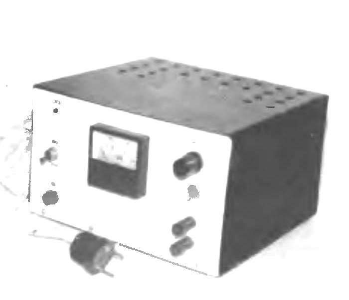
 Suggest a charger circuit for battery cars. Charging current of 5 — 6 a, the voltage at the output 20 V. the Circuit provides a smooth stable run, simple to technical solution, and most importantly, the device can be easily manufactured at home. Properly collected scheme of known-good parts does not require adjustment.
The charger consists of a transformer T1, rectifier VD1 — VD4, control thyristor VS1, the scheme of its control (of the elements (R1, R4, C2, VT2, VTЗ, R7, R8, VD10, T2) and the scheme of regulation and stabilization of the output voltage (consisting of R5, VD9, R9, R10, VT1, VT4, R12, R13, R14, C5, R15, R16). The output voltage is filtered by capacitance C1. The elements R3, C3, C4 required for a smooth launch of scheme stabilization and smooth control of the output voltage. The power scheme control thyristor VS1 is a variable voltage coming from the windings 19 and 20 of the transformer T1, rectified by diodes VD5, VD6 and VD7 stable. Resistor R6 sets the current going to the Zener diode VD7. The circuit R1 — HL1 is only for display on the device. The output voltage measured by the voltmeter РV1 30 V, and load current — ammeter PA1 10 A.
The principle of operation of the battery charger following. The AC voltage from the winding 13 — 14 is rectified by diodes VD1 — VD4 and acts on the regulating element is a thyristor VS1, which is controlled by the scheme collected on VT2, VTЗ — analog odnoimennogo of the transistor. The voltage taken from the windings 19 and 20 of T1 is rectified by diodes VD5, VD6 and VD7 stabiliziruemost. This voltage charges C2 through R2, R4. The dividers R7, R8 sets the potential on the base of VT2. As soon as the voltage on C2 exceeds the voltage VT2 on the basis of 0.7 — 0.8 In, opens VT2, VTЗ, and transformer T2, winding 1 — 2 there is a pulse, which induced in the winding 3 to 4 and open VS1. Voltage with rectifier to charge C1.
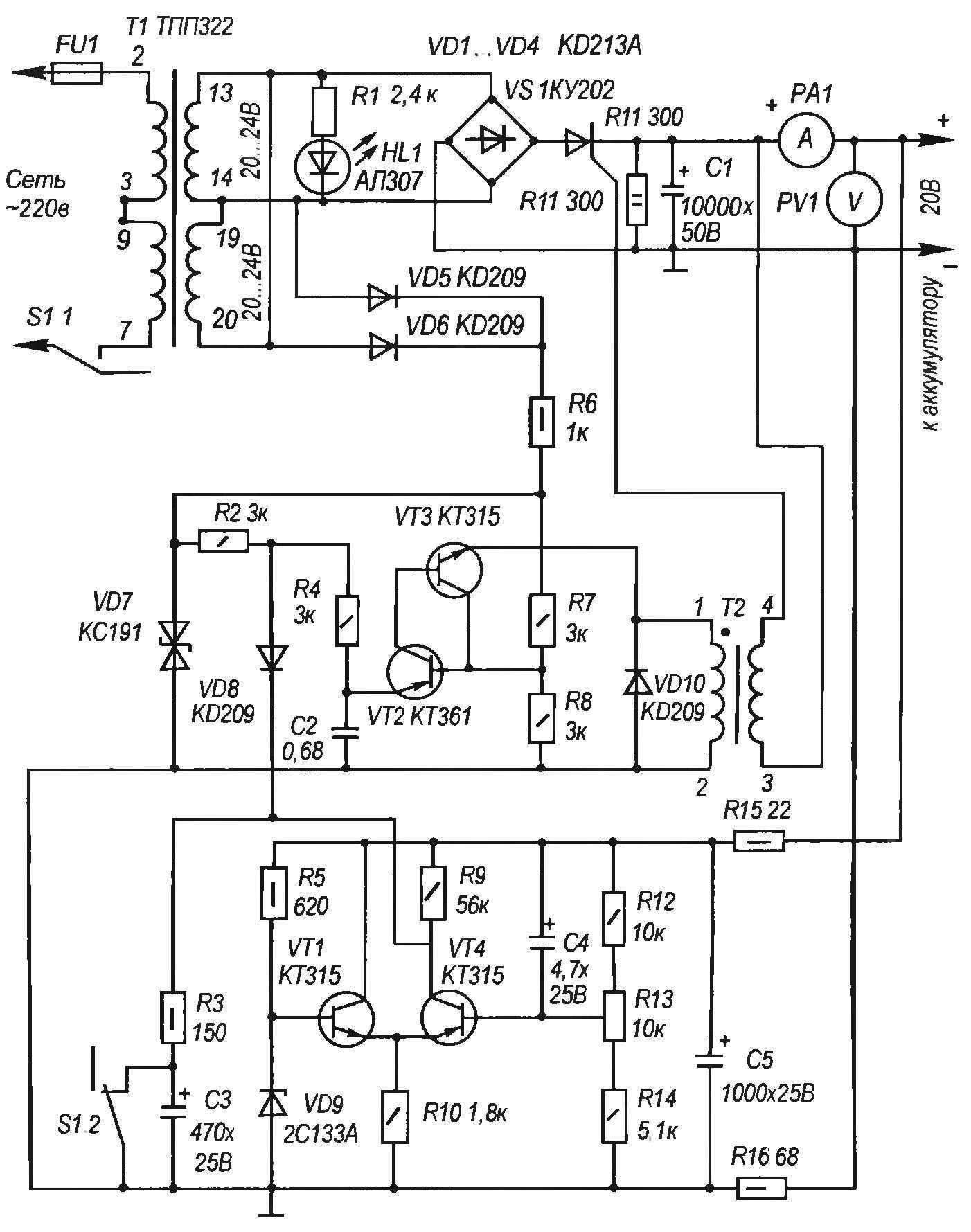
Circuit diagram of charger
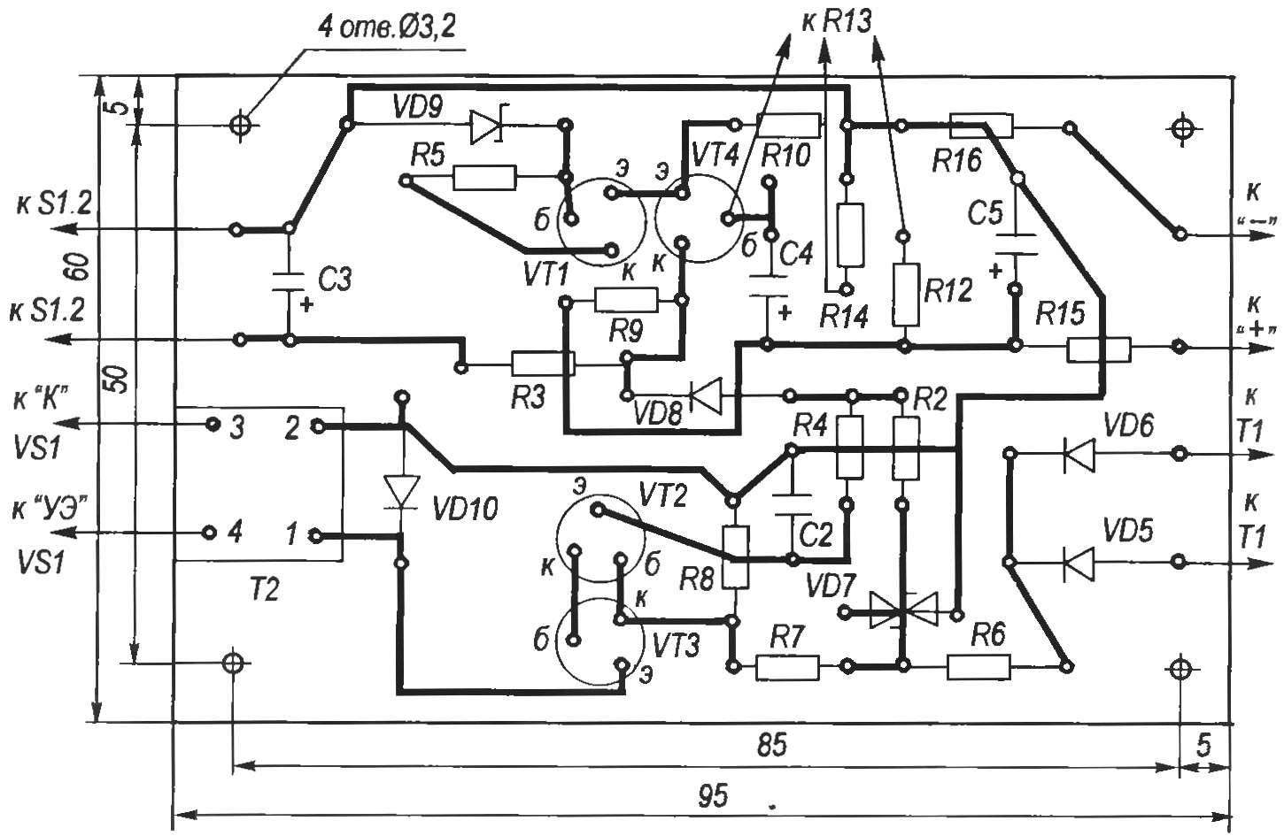
Assembly drawing
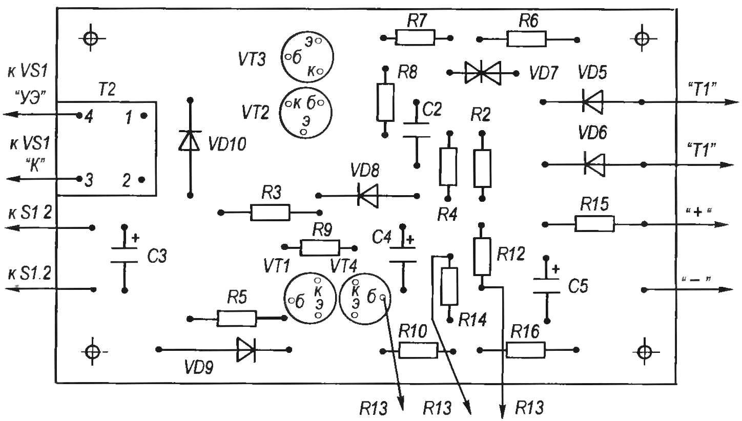
A printed circuit Board,
The stabilization circuit consists of a differential amplifier VT1 — VT4. The voltage at the base VD9 VT1 stable. By changing the position of the engine R13 is changing the voltage on the base of VT4 and consequently the collector current VT4, which is the sum of the current that goes through R9 and VD8. This leads to changes in current and time of charging C2 to a voltage VT2 opening, VTЗ. C2 controls the time of the open state VS1, which determines the voltage on C1, that is, the output of the device.
The control scheme also provides the output voltage regulation. With the decrease in the latter due to an increase in load current will decrease the voltage at the base of VT4, and as a result, the current I to VT4, which consists of 2 parts: the current that goes through R9, and the current going through VD8. Therefore, the increase and the charge current of C2 — he used to charge to threshold voltage open VT2, VT3. Regulating thyristor is longer in the open state, C1 is charged to higher voltage, hence the output voltage will also increase.
When increasing the output voltage by reducing the current load of all the processes of operation of the circuit of stabilization occur in reverse order.
Details ZU
The transformer T1 with a capacity of not less than 200 W with a voltage at the secondary winding of 24V and a current of at least 6A.
The S1 toggle switch — MT-1-2.
The diode bridge VD1 — VD4 can be collected (except in the diagram KD213А) of diodes KD201А, KD203А, D231, D242А.
The thyristor VS1 must be rated for a voltage less than 50 V and a current of 10 A.
The transformer T2 can take the ready out of the throttle D13-8, or be wound on a ferrite ring: the ratio of windings of 1:1, wire diameter 0.3 — 0.4 mm, number of turns 40.
Capacitor C2 is of type K10-17A, electrolytes imported.
Resistor R13 type JS4-2M.
Resistors of the type ALT, MLT, C2-33.
The device PV1 — voltmeter on 30 In (type M4259).
The device RA1 — ammeter 10 A (type M4259).
The thyristor VS1 and the diodes VD1 — VD4 must be installed on the radiators.
Circuit Board made from glass fiber plastic with thickness of 1.5 mm.
Yu KURBANOV, Tula
Recommend to read
 “OPERATION POLAR BEAR”
Many historians of the Russian fleet passed the XIV century and goes straight from the campaigns of the Kievan princes to Byzantium if not Peter the Great, at least to the campaign of...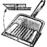 ETERNAL SCOOP
No words, plastic dustpan easier and more hygienic than metal. But its working edge for strength are made thick, and it is an insurmountable barrier for dust: not just a broom, even...
