 Remote from the television station areas, in zones of uncertain reception of television signals of meter (MB) and decimeter (UHF) ranges have to install industrial television broadband antenna of the type ASP-8W, “LOCUS”, “DELTA”. Each of these antennas comes with a amplifier which can have a different magnification strength of incoming signals and is chosen for specific conditions of admission (for example, SWA14 gives signal gain 32 dB, SWA9000 — 38, SWA1L — 8 to 10 dB).
The amplifier is mounted directly on the antenna in a protective from rain plastic case. His power supply 12 ±1 V is supplied from the adapter (also included in the antenna), are included in a separate outlet with a voltage of 220 V and supplied by the same high frequency antenna cable, which is passed back and the incoming TV signal. This causes unnecessary power consumption, the need to have an additional outlet and creates some inconvenience — at long breaks in TV, and hence the antenna, it is necessary to disconnect the adapter from the network, it is easy inadvertently to forget.
However, a separate power supply can be excluded, sapita amplifier from the TV. A simple device diagram is shown in figure, allows you to connect two or more television receivers to one antenna feed.
Experiments and operation has shown that when a voltage of 12 V, the additional load current consumption is only 15 — 40 mA (depending on antenna type) and does not lead to violation of normal operation of power modules TV.
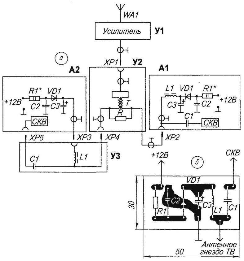
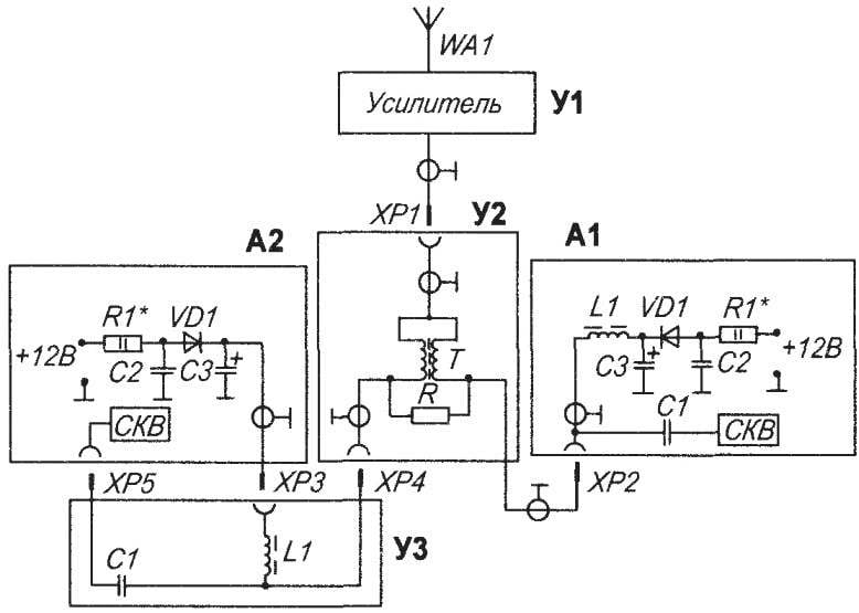
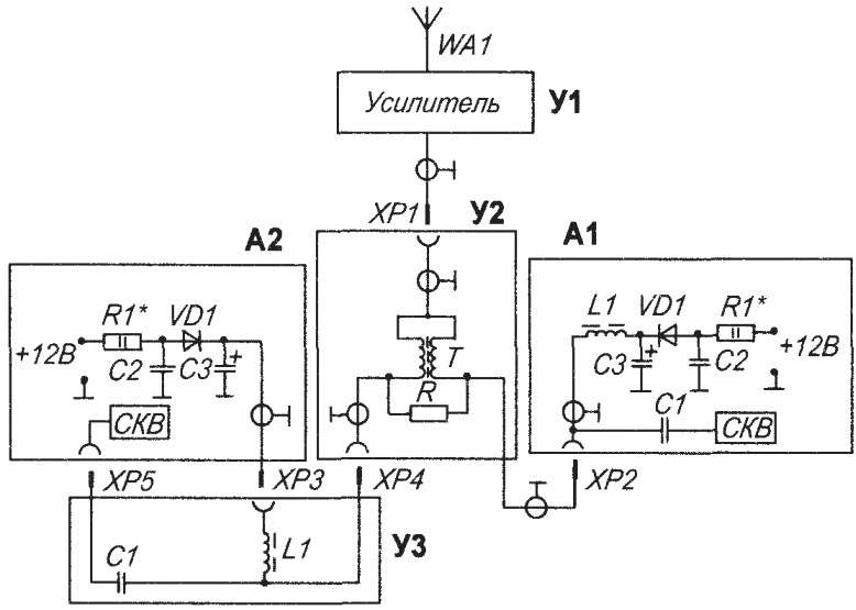
Electrical schematic (a) and PCB layout (b) device power amplifier of the broadband TV antenna designed for areas of uncertain reception of the signals MB and UHF bands when connected to the antenna simultaneously two TV sets:
WA1 — antenna (type ASP-8W; “LOCUS”; “DELTA”); N1 — antenna amplifier (supplied with antenna); U2 — unified TV splitter RTS MV+DMV; U3 hub (s ); A1, A2 — power supply aerial amplifier 1st and 2nd TV; R* is a resistance of 120 Ohms (selected); C1 is the capacitor 510 pF; C2 capacitor of 0.1 UF; C3 capacitor 100 µf (25 V); L1 — inductor PDM 0.1 to 100 µh; VD1 — diode КД808; ХР1 — ХР5 — antenna connectors
+12 V voltage from the output of the power supply module TV A1 through a current limiting resistor R1, the decoupling current diode VD1 and a high frequency choke L1, is supplied to the antenna Jack of the TV. Capacitors C2, C3 are elements of the low-frequency (LF) and high frequency (HF) filter aerial amplifier U1 associated with the antenna WA1. Amplified TV signal via connector ХР1 socket, splitter U2, aerial plug 2 and the socket of TV A1, the capacitor C1 is supplied to the selector of channels of meter and decimeter waves (SLE). Capacitor C1 is installed in the gap of the cable between the SLE and the antenna socket of the TV. To connect a second TV having an antenna connector, mounted directly on SLE, you need to make additional splitter v3 where to install the capacitor C1, and a voltage of +12 V on the amplifier to draw from the power supply module of the TV on a separate connector HRS. While high-frequency inductor L1 is better placed in the splitter.
For making homemade splitter v3 you can use a small plastic box in which to secure the antenna connector and locate capacitor C1 and choke L1. Limiting resistor R1* is selected so that when the whole antenna device, the supply voltage of the amplifier shall be not less than 11.3 V, and with a possible short circuit (the amplifier, plugs, jacks, cable) the current selection from the power module not exceeding 100 mA. The VD1 diode in the circuit it is advisable to choose low direct voltage drop (0.3 — 0.6 V). Suitable КД808; 2Д806А, 2Д806Б; FD600 etc.
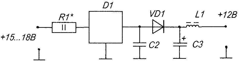
Schematic diagram of the antenna booster power supply / voltage regulator when you remove from the TV the voltage of 15 — 18 In
The material shows another diagram of the similar device in which module the power of the TV is removed the voltage is not +12 and +15… +18 V. In this case, the device must additionally include a chip voltage regulator D1 КР142ЕН8Д.
When you work the General pattern of the antenna power amplifier is from the power supply module of the TV that is turned on. When you turn on the power to the amplifier is supplied with two power modules. The connection between the power supply voltage +12V is missing due to the diode VD1 that is installed in each TV.
The circuit elements are placed on a printed circuit Board that is installed inside the TV, as close as possible to the antenna Jack. The total circuit is cable RK-75.
Mount Board is made thus: to the Cabinet track boards soldered the cut end of the copper single-wire length 40 mm, diameter 1.8 mm. Then the other end soldered to the body of the SLE. Mount the Board turned out quite reliable.
M. POVALYAEV, Yelets, Lipetsk region.
Recommend to read
 HARNESS-GASKET
If you are laying under flange of large diameter to cut from a camera from the wheels, as is usually done, will not work: it is twisted. Rescue and cords or braids of twine. I in these... MULTI-SPEED FLOATMATH
On our market there are now a lot of imported bikes with a large (over a dozen) number of speeds. But fascinating these machines are, perhaps, only youths. Experts understand that to...
