Each series winding is isolated 2-3 layers of oiled paper the transformer. The findings are soldered to the petals, located on the frame and mark.
Between the U-shaped halves of the magnetic tape, if necessary, lay 2-3 layers of capacitor paper, that the gap was 15-30 MK. Then the “hum” of a transformer will be much weaker. After Assembly, connect the power windings as shown in the diagram.
Transistors and diodes Д242 installed on the heat sinks (see Fig. 2) — aluminum plate the size of 90Х50Х1 mm in the first and two put together aluminum plates with a thickness of 2 mm for the second.
Fig. 2. Power transformer with established elements:
1 — heat sink for diodes Д242, 2 — heat sink for transistors, 3 — panel with diodes КД202М, 4 — panel with resistors RZ—R6, 5 — glinkova fee.
Instead of the transistor П4БЭ possible to apply ГТ701А, П209, П210, and instead П201 suitable П213, П214, П216, П217 with any alphabetic index. КД202М diodes can be replaced by КД202К KD202L or Д226Б, КД105 connected two in parallel; Д242 — КД206 with any alphabetic index or D243, Д244, D245; Д9Е — any series D2 or D9.
Capacitors C1, C2 C50-12 have a common housing. They can be replaced by any other with a working voltage of at least 350 V. Instead of capacitors C50-6 (Sz, S4) can be applied C50-3. Fixed resistors MLT-1 or VS-1.
S1 — push button switch from home appliances, S2 — toggle switch TS-1-2, S3, S4, S6 — app switches S5, S7 — toggle switch TV2-1.
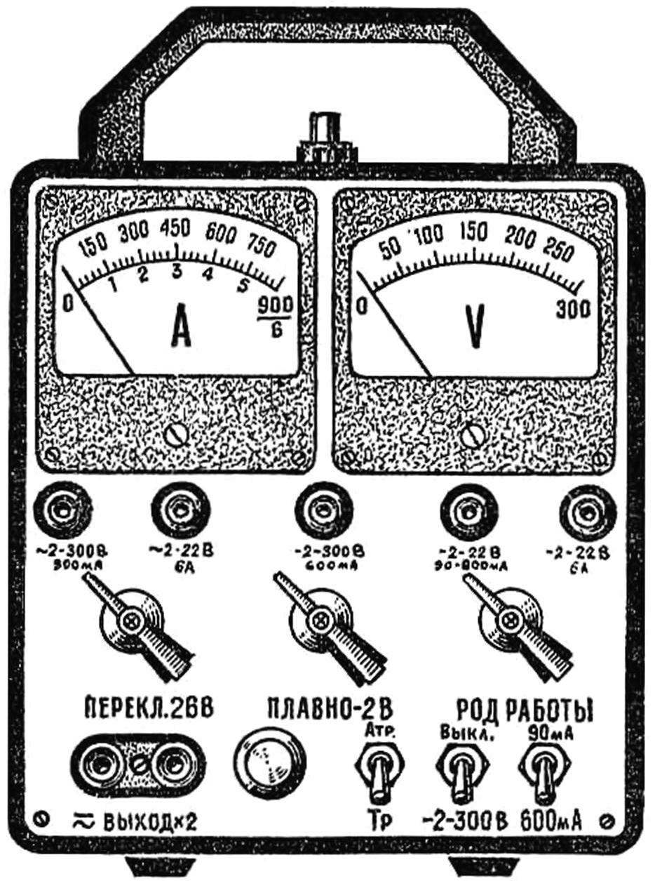
PV1 — voltmeter Ц4200 with a current full deflection 250 µa, PA1 — М4207 microammeter with full deflection current of 50 µa. These measuring devices can be replaced by any other within the specified sensitivity. The scale of Indicators is produced in accordance with the pattern of the common species.
Shunts R7, R9, R10 wound nichrome wire Ø 0,3 mm on the bodies of resistors VS-0.5, pre-remote conductive layer. The same wire, but Ø 0.15 mm are wound and shunt resistor R11. Shunts R8 and R12 represent segments of Ni-chrome wire Ø 0.7 mm and a length of 2-3 cm Nichrome wire can be replaced by manganin or konstantinovym, but the length of the winding then you need to increase two times, since the resistivity of these materials is less. Shunts installed on the switch S6.
N1—N5 — lamp commutator KM 2 is designed for a voltage of 24 V. They can be replaced by any other, clearing the appropriate voltage from the transformer.
The power supply is housed in a duralumin case size 190Х180Х125 mm. In its lateral walls made 7-8 longitudinal ventilation slits size 80X2 mm, and at the base is 2-3 hole Ø 20 mm.
Special chassis the unit has. Bearing elements serve as the front panel and the power transformer. The installation is made by wires gathered in bundles.
Faceplate size 180Х170 mm made out of sheet aluminum with a thickness of 2 mm. it imposed a sheet of Whatman paper with inscriptions in black ink, and covered the top with plexiglass thickness 2 mm.
A push-button switch S1 is mounted on top of the housing.
If the installation is done correctly and all items are serviceable, the power unit begins to work immediately after inclusion in the network. You will need to adjust only the magnitude of the additional resistors and shunts have dial indicators.
A. MEDVEDEV, Krasnoperekopsk, Crimean region
Recommend to read THE FUSELAGE FOR THE CAR Originally solved the problem of production of the fairing for racing córdoba in the box O. UFOs from the city of Ilyichevsk of Odessa region. He refused a long and laborious work with... LIGHT TANK T-70 In October 1941, it became clear that the new light tank T-60, serial production of which began earlier this month, almost useless on the battlefield, His armor freely fought all... 
 Every radio Amateur knows that without a source of constant and alternating stresses of different magnitudes in practical work is not enough. He needed to establish radiocontrole, repair equipment, charge batteries, test the motors and relays, to conduct physical experiments. All this is possible to do with a universal power supply, which we offer to the readers.