Important note. If the signal is received from the base hours is not the end, the scheme after unlocking again starts to work. Given this fact, the user has not to rush into a magnet. To his lomew^ you can use only thoroughly waking. But such a revival will inevitably occur, as practice shows, only the completion of action long staff of a buzzer.
The scheme is not critical to the choice of the majority of the details. Diodes VD2 and VDЗ can be direct current of 30-50 mA and a reverse voltage of about 50 V (for example, КД102, КД103, КД509, KD510, КД521А, КД521В, KD522). Acceptable also КД105, D7, D226, Д206-Д211, Д220, Д223, Д310 and other semiconductor valves with appropriate parameters, however, their use entails the necessity of redoing the PCB.
Approach to VD1 stricter. It is desirable that the selected diode has a small forward voltage (e.g., was germanium, type D9). Otherwise it is difficult to guarantee reliable operation of the device, especially when a partially discharged battery base hours.
Transistor VT1 should have h 21E > >40…50,Ik max >= 25 mA, IKE max>=25 V. such parameters are, for example, KT315, KT361, КТ312, MP20, МП21, МП25, МП26, МП37А, МП37Б, МП40А. When using the p-n-p transistors should be changed to the opposite polarity as the inclusion of a diode and connecting the input device to the buzzer base hours.
Relay self-made, assembled on the basis of serial magnetic reed switch CAM-2. The coil consists of 1500 turns of ПЭВ2-0.1. It is wound on a frame made of thick paper and put on the reed switch. To create a polarizing field use small-sized permanent magnet (e.g., magnetic reed buttons).
The main part of the device mounted on a printed circuit Board, which is made in advance of the 1.5-mm foil-tion of Micarta or PCB by cutting the respective insulating grooves in the conductive layer. ULM resistors, diodes D9 КД509 and set vertically. The findings of transistor KT315 and condenser KM solder, trying not to deviate from the recommended topology. Well, when you use parts other sizes are making the fee adjustments.
The cutout on the PCB is designed to relay coil. In the place circled in the sketch by the dashed line, is attached a magnet. Correctly assembled Board is placed in the housing, which can be a plastic box of suitable size, through holes in one of the side walls displays the four flexible wire type mgshv-1.
A couple of insights running in accordance with circuit and installation diagrams to the reference clock, connected to the contacts of the buzzer with the correct polarity, which is useful to clarify well in advance with a tester. And all because the manufacturers of cheap “electronics” are often guilty of mistakes in the legend of details on their products. The true polarity of the voltage on the contacts of the buzzer is determined by the deflection connected voltmeter at the time of arrival of the sound signal from the alarm, not yet docked with the console. The very same dock, you can perform all-in-one, connecting the wires to the contacts of the buzzer, or split, for which the watch case is set microresearch, and the entrance console is equipped with microvilli (illustrations plug-fork option is not shown).
Setup of a homemade device is reduced to the selection of the optimal placement of the magnet, which find, gradually moving to the last ger-stake. At the time of “clumping” of the sealed contacts note the location of the magnet. Then slowly begin to push on far enough to open the reed switch. Equidistant from these “critical areas” and is an optimum, where the magnet is glued to the Board.
The value of the resistor R2 is selected for reliable relay operation. But we should not get involved in the search too little resistance, because it can lead to extremely large collector current when the transistor VT1.
D. VOLKOV,Shakhty, Rostov region
Recommend to read
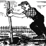 Plowing… with a shovel
I made this soil-working tool to lighten the hard work, since digging the ground with an ordinary shovel—constantly bending and straightening—had become harder and harder over the years....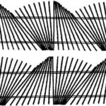 MORE ABOUT THE “DRUNKEN” FENCE
Readers interested in published in the journal some time ago. Linaeve from the eagle about the original decision stamenkovi fence in the suburban area, many asked to elaborate on her...