Velocity head, the perceived sensitive element of the sensor, the parameter which directly depend on the aerodynamic forces and moments acting on the wing of the glider. This parameter, note the device that uniquely identifies the gliding angle and position of the control stick regardless of air density (temperature and pressure).
Values for the limiting speeds are dependent on matching the stiffness of the working springs of the stem (pin-razmechtalas groups) and area of the diaphragm sensitive element of the device. These values are equal to 28±2.5 70±2.5 km/h, the selected adjustment of the degree of compression of the springs, altering the position of the contacts of the sensor.
The sensor housing (Fig. 1) consists of flat caps — a dull and drained and a cylindrical side wall, cut the height in two. The first cover by means of rivets attached to the tube of the receiver air pressure, the second contact group with lead wires for connection to the sound generator. Between the parts of the side wall is clamped a rubber diaphragm glued to a thin aluminum disk. The design is fastened by means of screws, nuts and washers. In the center of the disc and are fixed with nuts M4 stock with an internal spring. Smooth shank of the rod moves freely in the guide hole of the bracket, riveted to the bottom cover. The upper part with a thread and zakonchennoe the contact washer out of the sensor body through the Central hole drained the caps. With the retaining nut of the drive it locks the inner spring, the ends of which abut the disk and the centering plate. To reduce friction, moving in the Central hole of the cap section of the rod should have a smooth surface. Designed for stock pin grind and grind, holding in an electric drill Chuck. The resulting backlash of stock in the centering hole of the plate, as shown, does not impair the efficiency of the device.
Fig. 1. Sensor design:
1 — a blank cover, 2 — tube receiver air pressure, 3, 4 — cylindrical side wall, 5 — drained cover, 6 — membrane (diaphragm), 7 — drive, 8 — foiled textolite plate, 9 — bracket, 10 — insulating bushing screw, 11 — adjusting screw 12 — nut, 13 — terminal, 14 — outer spring, 15 — М3Х15 screw (2 PCs.), 16 — washer Ø 3 (2x), 17 — nut M3 (2 PCs.) 18 — the textolite washer Ø 3 (2pcs), 19 — Bush textolite, 20 — textolite plate, 21 — centering plate, 22 — wire signal minimum speed 23 — signal wire maximum speed, 24 terminal shell, 25 — М3Х50 screw (5 PCs.), 26 — washer Ø 3 (5 piece), 27 — nut M3 (5 PCs), 28 — pin washer, 29 — internal spring 30 stock, 31 — nut M4 (4 PCs) 32 — a guide clip, the 33 — rivet (2 PCs.)
The electric circuit of the signals corresponding to maximum and minimum speeds, the commute, the contact washer and the upper end of the rod. The first is an ordinary brass washer soldered to the Ganka. Fixed contact system consists of a metal bracket with adjustable screw and glinkovo sleeve. This node is attached to the top cover screws and ganks with the use of insulating washers and bushings. With contact of the puck is touching the foil surface glinkovo the plate, to which is soldered the signal wire to the minimum speed. Terminal of the carry out signal of the maximum speed is fastened with the nut of the adjusting screw. Between it and the upper end of the outer rod is spring centered and the contact washer insulating bushing screw.
When installing the sensor on the pipe side of the trapezoid of the glider it is necessary that the axis of the rod was parallel to the plane of the earth — then the influence of the weight of the moving parts of the rod on the accuracy of the sensor will be minimal. Arising from this mismatch of the sensor signal with the set values of the minimum and maximum speed of the glider does not exceed the value of ±2.5 km/h.
When the contact washer for the foil surface of the plate, the outer spring is fully decompressed, and the inside is so compressed that in the absence of excessive differential pressure on the diaphragm (zero speed) on the shaft and the disc acts a force equal to the product of the effective area of the diaphragm at the minimum velocity head corresponding to allowable small value of the speed of the glider. With the increase of speed force of the disk against excessive differential pressure exceeds the force of the compressed internal spring and rod, drifting, opens the circuit of the signal minimum speed. A further increase of this parameter, and the movement of the rod causes compression of the outer spring. When the glider is flying with the maximum allowable speed, the force on the disk from excessive differential pressure is balanced by the efforts of both compressed springs, until the rod touches the end face of the adjusting screw. Full working stroke is 6.5 mm.
Ask the exact dimensions of all the parts of the sensor does not make sense, since most of them can be carried out arbitrarily in consideration of the available scrap materials. Given only the data of those parts depends on the performance of the device.
The disc is made from sheet material D16T with a thickness of 0.5 mm. Diaphragm made of a rubber sheet with a thickness of 0.5 mm, for example from cuff surgical gloves.
Guarantee performance of the sensor is the presence of corrugation on the diaphragm (Fig. 2) not impede the movement of the disk in the enclosure. To utformat such corrugations, using both parts of the cylindrical side wall as follows. The blank cut on the outside diameter of the side wall (Ø 136 mm), firmly attached with glue 88Н to the end of one of the halves of the cylindrical wall. In the diaphragm cut circular Central hole Ø 40 mm. Then the bonding surfaces of the diaphragm and disc put a layer of glue 88Н and slightly dry (yet will not stick to the fingers). Next to the disk after the glue completely hardens, put a weight of 2 kg for stretching the diaphragm. The edge of the Central hole is shifted to the periphery of the disk. Obtained in this way the corrugations are quite suitable for the diaphragm in the sensor.
Fig. 2. The scheme of formation of corrugation on the diaphragm from sheet rubber:
1, a side cylindrical wall, 2 — diaphragm, 3 — disk, 4 — load, 5 — fastening screw 6 — bearing.
Part of the cylindrical side walls can be cut with a jigsaw from plywood, and both cover cut from a sheet of D16T with a thickness of 2 mm. sensor will fit the springs from the brushes of electric motors of vacuum cleaners, they can be made of steel wire Ø 4 mm. Diameter round internal spring — 8 mm, pitch of the coil is 2 mm, the length in the uncompressed condition 27 mm, the compressive force of 110 g to a size of 16.5 mm. the Outer spring has the same diameter and pitch coil, and internal. But the length of CE in the decompressed state is 22.5 mm, and the force of compression to a size of 16 mm is 70
Tube Pitot-made of pipe (D16T) size 12X1 mm Stem and the adjusting screw is made of brass or steel studs Ø 4 and Ø 6 mm respectively. To protect it from contamination and mechanical damage of the contact group it is covered with a protective casing, such as plastic cap from the aerosol container (shown in figure 1, dashed line).
In the device, you can use the generator of the audio signal, made by either of the two concepts (Fig. 3). Beeper tone pick up with the help of variable resistors R2, R3 (option a) and R1, R2 (option B).
Fig. 3. The schematic diagram of the generator of the sound signal.
Sound generator with power supply — battery “Krona” (option a) fit in an enclosure the size 30X60X80 mm and weight 100 g.
Moments of trigger contacts depending on a predetermined value of air speed select the adjusting screw and the change of positions of the contact washer, and the disk on the stock. Before installation on the glider sensor blow air flow in the opposite on a moving vehicle (a motorcycle) by controlling its operation by the signals in the head phones in accordance with the speedometer display.
MIRZABAEV V., candidate of technical Sciences, Gorky
Recommend to read SPRAY AT HOME In your magazine (No. 5, 1974), we wrote about how to extend the life of the aerosol can using a Bicycle valve. Here is another diagram of a homemade spray paint suggested by our reader... FIGHTING TODAY AND TOMORROW Air combat... the Popularity of this class has been and will remain unchanged. Let some say that today to do battle is not so "prestigious" — the whole world goes to RC vehicles, and... 
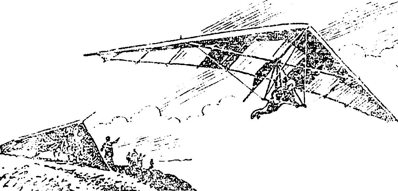 The gliders don’t need to explain how important the safety speed indicator. Such a device is especially valuable for beginners: its tip in a timely manner saves the pilot the novice from fatal errors in the management of the aircraft. In hang gliding, apply sound speed indicators. Our magazine has already told about similar designs (see “M-K”, No. 3, 4, 1982, “the Speedometer on a hang glider”).