
 The convenience of wireless remote control (RC) is undeniable. You can use them, without getting up, and the most interesting channel to enable, and the hardware on it to adjust according to the individual characteristics of perception.
However, not all appliances so perfect remotely manageable, as we would like. I managed to find a technical solution that can control any object that can and must be managed.
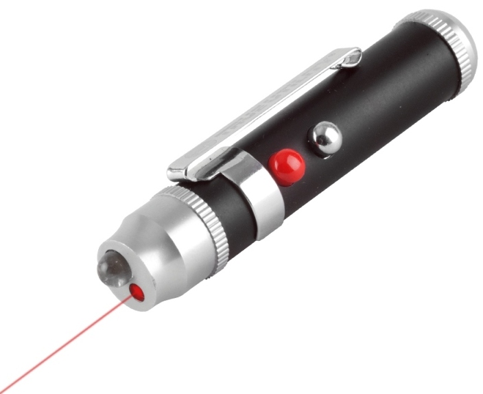
My device is a console, which is inserted between the wall power electric outlet and plug with power cord for the radio (as well — lighting, heaters, fans and other control objects, selected at the discretion of the owners). As the remote control is a miniature laser pointer (see, for example, “modelist-Konstruktor” No. 12,’01), giving a sufficiently powerful and narrow beam of light to the sensor actuator.
But a laser pointer without any reconstruction capable only of the same type a brief flash, and for remote control of electrical appliances must have at least two distinguishable commands (“turn on” and “off”). So, you need a special e-broker. Located between the photodetector and the power switch, it will convert the sequence of perceived pulses in alternating on and off load conditions.
The desired algorithm in the proposed development performs a logical elements 2I-NOT chip DD1 (К176ЛА7). Cell DD1.2—DD1.4 form two arms of the counting trigger. When his inputs give the same signals at the output of the alternating high and low logic voltage levels (log. 1 and the log. 0). This happens if VD1 on the photodetector (photodiode ФД256) get the flash of light pointer. Changing the trigger output signal controls (via the amplifier executed on the VT1 transistor) solid state relay VS1 and connected load.
In the initial state until sensor is VD1 is not lit, its DC resistance is very large. Accordingly, the high at the photodiode and the voltage drop. Acting on inputs 1 and 2 cells DD1.1, it provides at the output 3 of the presence of the log. 0.
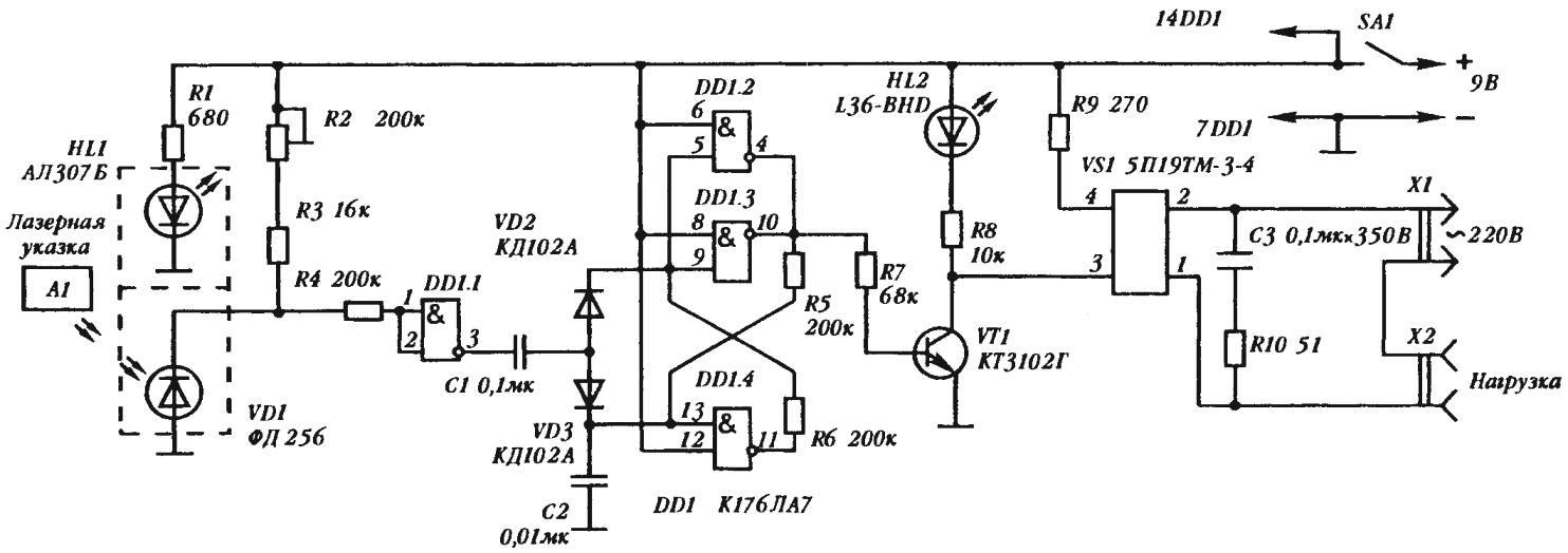
Electrical schematic of a homemade device controlling household appliances using laser pointer
At the inlet 13 of the cell DD1.4 at this time is also log. 0, formed due to the uncharged capacitor C2 at the time of switching the voltage, and the output 11, respectively, the logic of operation of this cell sets the potential of a high level. The latter, together with the power supply, ensures the presence of the log. 1 on all inputs cells DD1.2, DD1.3, a low-level signal at their outputs (4, 10) — captures the initial state of the cell DD1.4.
So, at the outputs 4 and 10 of the microcircuit DD1 will log. 0, creating the conditions for retention of the transistor VT1 is in a locked condition. As a result, the current in the opto-node relay VS1 missing, and his power triacs locked, de-energizing the load connected to socket x2 (mechanically operated switches of home appliances connected to this unit, must be transferred in the enabled state).
However, should the beam of a laser pointer briefly to get to the sensor, like resistance VD1 and the voltage will drop considerably, leading to switching cells DD1.1. Now its output 3 will be set to log. 1. This signal may not change through the diode VD2, the condition of the cells DD1.2, DD1.3 (on their inputs already have a log. 1). But, once through the diode VD3 at the output 13 of the chip DD1, log. 1 will cause the switching cells DD1.4. Now low-level output signal 11 will make cells DD1.2 and DD1.3 also abruptly change its former state. Gap created by the 4 and 10 outputs high-level signal opens the transistor VT1, which will revive inside the optocoupler VS1 and include in there the power triac, and with them — and attached appliance.
The following light team will repeat the reaction of the elements VD1 and DD1.1. Only this time log. 1 output 3 restore the previous state of the inputs 5 and 9 cells DD1.2 and DD1.3; accordingly, fallen to the outputs 4 and 10 voltage ban the VT1 transistor and VS1 across the relay will turn off the load.
For more convenient use of the device in a circuit scheme introduced a number of supporting elements. In particular, the lit indicator HL1. Combined with the detector VD1, submitted to user-friendly from floor level, it tells the user where specifically to send the beam of a laser pointer to control home appliance.
To the auxiliary elements of the device applies HL2 indicator of the stay of the load (e.g., heater) in the on state. This is a very convenient tip-a reminder to the user about the need to disconnect the appliance when finished or before leaving the owners of the house.
It is desirable that as HL2 used the so-called flashing led L36-BHD (L56-BHD, L56-L56 or BGD-BYD). When voltage is applied it begins to erupt with a frequency of about 2 Hz, making the indication more visible (thorough publication of such light emitters, see, for example, “modelist-Konstruktor” No. 12’99 ). If the flashing led to get you can not, then it can replace conventional АЛ307В. giving the green color (unlike red y emitter HL1). In the latter case, R8 is a resistor with a resistance of about 330 Ohms.
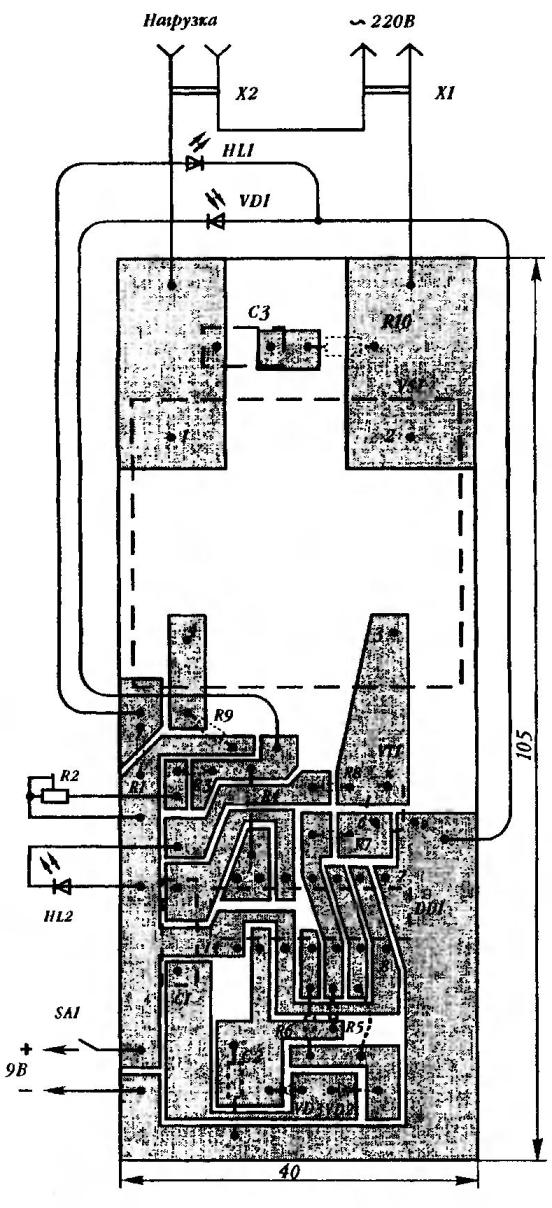
Circuit Board with a conventional image of desoldering electronic components
Since the resistance of certain electrical appliances (e.g., fans) has a predominantly inductive character, extent to protect the power triac relay VS1 from possible with this surge in the schema introduced an additional circuit C3, R10.
The power recommended from the power adapter with a voltage of 9-10 V. If desired, as a source of electricity to use two series-connected galvanic batteries type 3R12. In this case, for the sake of increasing efficiency, should abandon secondaction HL1, HL2 and their associated resistors R1, R8.
To assemble the device used (in addition to the already mentioned radio types) constant resistors MLT-0,125 (R1, R3-R9) and MLT-0,5 (R10), “podstreshny” SP-0,4 (R2), capacitors K73-24 (C1), KLS (C2), КП31П-4(S3), the switch П1Т-1-1. Almost all of them are placed on the Board of one-sided foil plastic. Case — style plastic “soap dish”; in the walls of pre-drilled several rows of ventilation holes with a diameter of 3-4 mm, and from the end near the relay VS1, set socket x2 for connection to the load. Bred out of the housing, the knob of the variable resistor R2 is used to adjust the threshold of the cell DD1.1.
The led-pointer HL1 and detector VD1 located on a remote base, linked to the cost of a cord of suitable length. Non-removable cord, tucked into the plug, the device is connected to a wall outlet.
Yu PROKOPTSOV
Recommend to read
 AIROPLANES FROM SVERDLOVSK
This picture was sent to us aircraft from Sverdlovsk V. Babs. Of course, you have learned winopener, the description and drawings which were published in No. 8 of our journal in 1970. ... AND WATERED, AND WATERED
In the house of the manor type of water demand is far higher than in a city apartment. Because usually when there are a garden, vegetable garden, and every fowl in the yard, which water...
