 Informing about the occurrence of an event, people often use sound signals. Usually they have the character of a continuous sound “one note” annoying “beep-beep” or howling siren with a periodically varying frequency. Generators of electric vibrations, producing these signals is also straightforward. They are based on one-two multivibrators, which makes the structure very simple, accessible to even beginners repetition hams.
Not “getting stuck” in a continuous monotone sound, not enough attention-grabbing and able to get lost among the other noises, we emphasize that the other two (“beep-beep” and siren) have a common property — to create an acute sense of danger (and sometimes fear) from those to whom they are addressed. Alarming signal is justified if it manifests, say, fire, burst pipes, gas and water supply. But this sound completely out of place when you want only “quiet household” information (e.g., the appearance in the zone of propagation of the signal exactly what are you currently waiting for).
“Gentle” signal, according to many, must be musical. Even better, if this is a fragment of a familiar tune. By the way, these “soft” signal can be used to alert about an accident if it is not desirable to devote all the vicissitudes of the disturbing situation of those among them may be people with weakened psyche.
As novice Amateurs to make a generator tunes at home difficult, it makes sense to use a ready available product — the so-called “musical postcard”. A colorful cover here is hidden a miniature device that plays the programmed melody. It is a small circuit Board with a special chip, “tablet” galvanic power source, and piezoelectric alarm, giving you the opportunity to listen to a piece of music directly on the place where it is synthesized (a detailed material about these devices, see, for example, in No. 2’2003 “Model construction”).

The schematic of the alarm device issuing the broadcast is not boring annoying or disturbing the soul of the signal, and a tune from a musical greeting card A1:
1 — electronic Assembly musical greeting cards; 2 — current collectors for power supply; 3 — a socket for a regular galvanic battery-“tablet”; 4 — a-chip”drop”; 5 — PCB musical greeting cards; 6 — the piezo
Remains, in fact, not much is to convert the generated musical postcard Electrosignal sound frequencies in the modulated accordingly radio waves that can be perceived and reproduced in the form of tunes ready radio. This is easiest to implement in the FM band, using a simple to manufacture transistorized transmitter with frequency modulation.
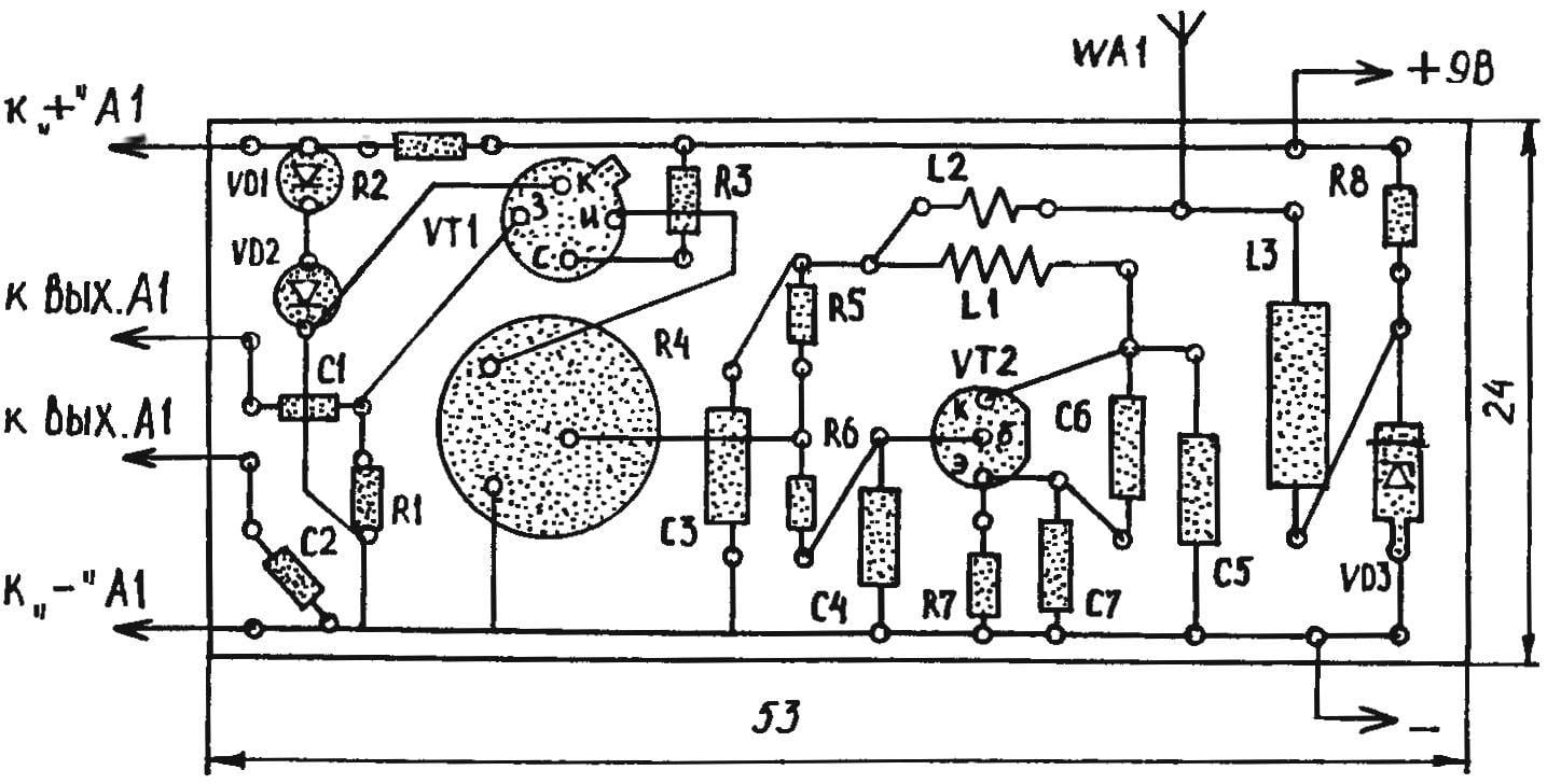
The generator for such a transmitter can be collected even on the widespread КТ316А transistor on the circuit diagram (Fig. 1) well-known to many radio Amateurs. Oscillations with a frequency of about 87.9 MHz are specified here, the resonant circuit L1С5. Antenna WA1 associated with inductively through coil L2. The inductor L3 prevents the outflow of the transmitted signal to ground through the power supply circuit.
Since the output Electrosignal sound cards A1 is designed to work with high impedance load such as the piezo, so far to reconcile with the relatively low-impedance input of the radio-frequency generator includes a special stage FET VT1 is operating on a source follower. Introduced in the output circuit of the latter variable resistor R4 allows you to adjust the modulation level.
To minimize the influence of possible fluctuations of the supply voltage on the RF generator, provides stabilization of the transistor VT2 through the Zener diode VD3, and Usup coming from the batteries GB1, taken approximately twice higher than in less protected similar devices. Group R2, VD1 and VD2 essentially is also the stabilizer, but its main purpose is to downgrade to a 1.5 V voltage supplied to the “music” node A1.
The device is triggered by a contact closure push-button switch SB1, while the staff switch musical greeting cards must be shorted by jumper wire (POS. Figure 3. 1). If you need to start radiosignalizatsii of any specialized sensor, the switch output is set to the last place mentioned jumpers, and push-button element SB1 is replaced with a switch with two fixed positions.
Contour coil L1 is frameless, is wound on the mandrel with a diameter of 2.5 mm To achieve the required inductance, there is enough of eight turns of wire ПЭВ2-0,3. On top of the coils L1 and L2 is a double made from the same wire. But a high frequency choke of appropriate to take a ready-made, brand DM-0,1.

Circuit Board transmitting the suit of the alarm (radio, located on the reverse side, a conventional image of “the enlightenment”)
As resistors are suitable cheap, widespread MLT-0,125. The same is the approach and the selection of capacitors: C1 and C2 — type KLS, as others successfully cope PM-1.
Powering the device from the “Crown” and similar galvanic battery. Antenna — telescopic pin from the small receiver.
High frequency generator and matching cascade assemble on a circuit Board from a one-sided foil plastic 53x24x1 mm (Fig. 2). The width of the conductor paths of the order of 2 mm. At the nodal points where are performed the drilling under the findings of the parts and their wiring, are provided pads in the form of circles with a diameter of 3-4 mm. Themselves radio are located on the reverse side of the Board. The case for transmitter “musical greetings” from the air can serve as a plastic box type “soap” sizes.
Debugging is simple. First to organize a “communication channel” configures a radio. It is desirable that near a fixed frequency manufactured by transmitter not auditioned interference from other, often more powerful radios. Then, by aligning radiograbador: the convergence of the splitting of the turns of the coil I. the accuracy of the adjustment is controlled by the dynamics of sound radio, from which will flow the melody is derived from ether in accordance with the program, “hardwired” in the electronic memory musical greeting cards.
Yu CASKIN


