
 There are electric circuits of high voltage sources for aeroionizatora, which are collected on the basis of the automotive ignition coil. They are all quite simple and easily repeatable. However, the cost of the ignition coil is very high.
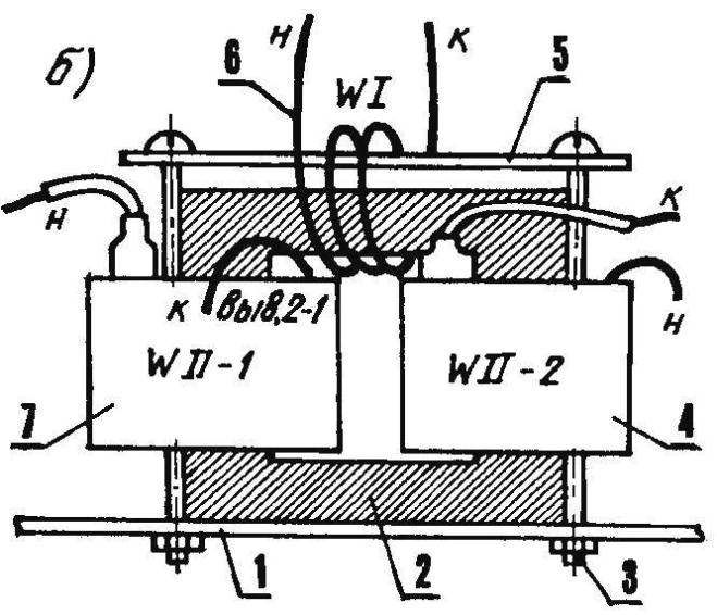
I also find the scheme a high voltage power supply in which the ignition coil uses the transformer containing the high voltage winding from two ТВС110ЛА old black-and-white TVs. To do this, the base fuel assemblies are removed and the primary one ferrite core to put on both the high voltage winding. Further, the transformer is going with subsequent contraction of one of the brackets by which Twsy was attached to the TV.
Between the two high voltage windings on the free space used ferrite core (directly on top of the bracket) is wound the primary winding of the XVI wire mgshv-0.35 mm. It should contain 10 turns.
The findings of both the high voltage windings WII-1 WII-2 properly, Spazio-VAT so they worked as a single unit. For this purpose, the conductors which have high voltage insulation, is connected to the voltage multiplier, and other findings connected to each other.
The voltage multiplier also contains the details of the underlying black-and-white TV is a high — voltage capacitor filter circuit of the anodes of the tubes. They have a capacity of 470 pF.
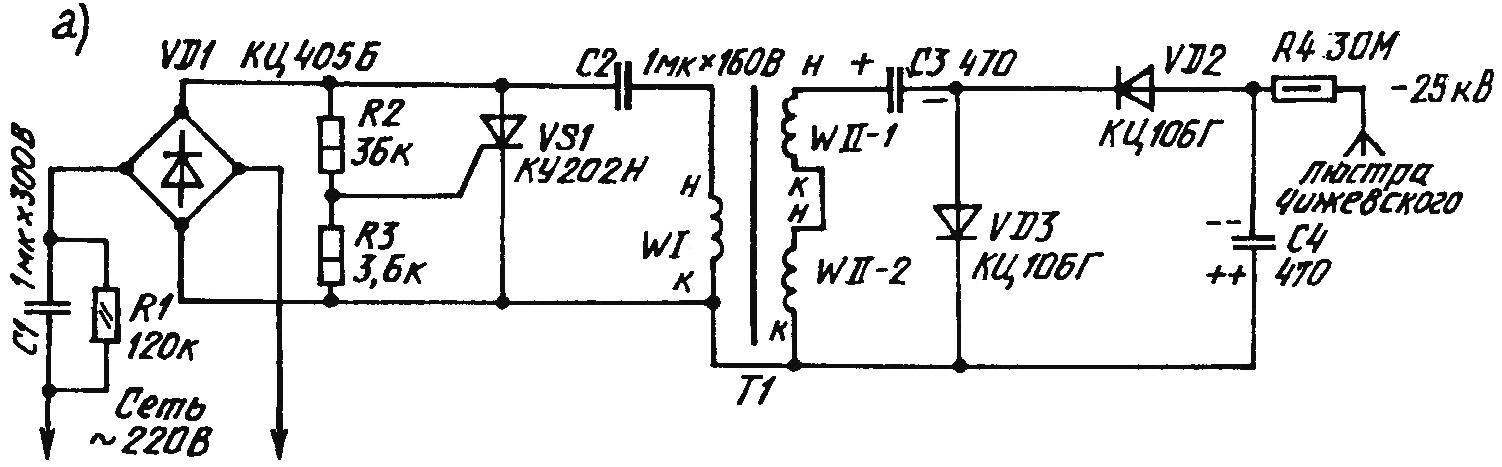
As the rectifier bridge VD1 is the best work is widely known КЦ405Б. The thyristor VS1 is also not rare, but it is desirable to have headroom voltage. Suitable, in particular, КУ202Н. Both diode voltage multiplier — КЦ106Г.
The capacitors C1 and C2 it is better to use 1-microfarad, brand MBGC-1. Operating voltage the first of them should be of the order of 300 V, the second— 160 V. Is MBGC-1 can be applied К42У-2, well-established in many Amateur radio designs.
A circuit diagram of a source of high voltage (a) generator of negative ions and the transformer (6), without which the proposed “electronics” would not work:
1 — circuit Board (sheet of thick cardboard, plywood or fiberboard); 2 — ferrite magnetic core; 3 — pinch bolt and nut; 4 — the second half of the high voltage winding; 5 — bracket; 6 — primary coil (10 turns of wire mgshv-0.35 mm); 7 — first half of the high voltage winding; det. POS. 2 — 5,7 — ТВС110ЛА black-and-white tube TVs; the designation of the terminals of the windings according to the wiring diagram
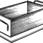
The device can be mounted on a sheet of thick cardboard, plywood or fiberboard, then inserted into a translucent plastic box from under the cake. For the convenience of the individual sessions (aeroionization procedures) instead of a chandelier of Chizhevsky use a special “balneological” electrode of soft copper (annealed), 2 mm wire and place it in a vinyl chloride tube or flexible hose from a medical dropper. At the end of the electrode should be brush — supplier of medicinal ions, made of 5 pointed 6 copper conductors with a diameter of 0.31 — 0.51 mm and a length of 35 — 40 mm.
Correctly executed, the device no configuration required. It will be enough to include it in household electricity — and start to work the electronics…
Positive (after the rectifier bridge VD1) current pulses will charge the capacitor C2 through the primary winding WI of the transformer T1. However, in parallel with the rectifier included thyristor VS1, a control electrode coupled to a voltage divider R2R3. Once and reaches 5 V, the thyristor opens and closes the capacitor C2 to the primary winding of the transformer.
While VS1 is opened, the chain that contains WI, undergo damped oscillations. The resulting in the secondary winding, consisting of the WII 1 and WII 2, high voltage pulses are applied to the voltage multiplier, operating in the following algorithm. If the first (say, positive) pulse passing through the diode VD3, capacitor C3 charges to a rather high potential, the second (negative), becoming almost in 2 times is more due to the voltage boost from C3, going through the circuit containing diodes VD2 and C4. It turns out that the output capacitor C4 is charged to a voltage of 25 kV, “minus” which, coming through the 30-Mahony resistor on the chandelier Chizhevskogo (or “balneological” electrode), creates the conditions for the emergence of healing air ions.
Despite the fact that the thyristor VS1 closes the “secondary” output circuit of the rectifier bridge VD1, a critical situation for working here gate p-n junctions does not occur. After all, consistently (for “primary” circuit of the bridge) as a damping resistance included in the capacitor C1.
A. PARTIN, Ekaterinburg
Recommend to read
 AND YOU DON’T NEED PALNT
If you are going to build something: garage, sauna, shed, and maybe the house, but you lack the materials, cinder blocks, made with your own hands, you'll come to the rescue. Need form... AND RACK AND PARTITION
It is generally accepted that a square room is much easier for furniture placement, looks better. In this sense, we are not lucky to have got the so-called "pencil case", 3X6,3 m. to...
