 Unusual sounds and sound effects using simple electronic consoles on-chip CMOS that is able to capture the imagination of readers.
The scheme is one of such boxes, presented in figure 1, was born in the process of various experiments with the popular CMOS chip К176ЛА7 (DD1).
This scheme implements a cascade of sound effects, especially from the animal world. Depending on the position of the engine variable resistor mounted on the circuit’s input, you can get almost real to the ear sounds: “croaking frogs”, “Nightingale trill”, “meowing cat”, “the bellowing bull”, and many others. Even the various human unintelligible combination of sounds like a drunken exclamations, and others.
As you know, the nominal voltage of this IC— 9 C. However, in practice, to achieve special results may deliberate decrease of the voltage to 4.5—5 V. In this scheme remains operational. Instead of the chip 176-series in this embodiment, it is appropriate to use and its more widespread counterpart series К561 (K564, К1564).
Fluctuations in the sound emitter BA1 are served from the output of the intermediate logic circuit element.
Consider the operation of the device in the “wrong” power mode— with the voltage of 5 V. as a power source you can use the batteries from the elements (e.g., three AAA batteries connected in series) or stabilised mains power supply unit is installed at the output of filter—oxide capacitor has a capacitance of 500 µf with a working voltage of at least 12 V.
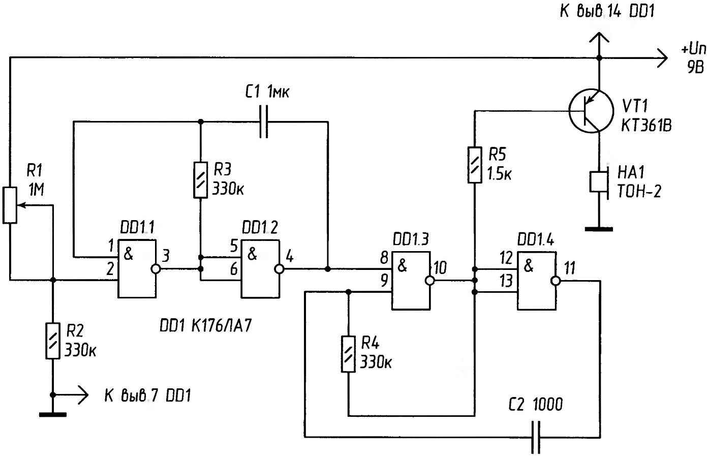
Fig. 1. The electrical circuit of the “strange” sound effects.
On the elements DD1.1 and DD1.2 assembled pulse generator that runs “high voltage” at pin 1 DD1.1. The frequency of the pulse generator, audio frequency (AF), when using these RC-elements, the output of DD1.2 is 2-2,5 kHz. The output signal of the first oscillator controls the frequency of the second (assembled on the elements DD1.3 and DD1.4). However, if picking up pulses from terminal 11 of the element DD1.4—will be no effect. One input terminal of the element is controlled via a resistor R5. Both generators work in close conjunction with each other, snowslides and its dependence on the input voltage in an unpredictable pulse packet at the output.
With the exit of the element DD1.3 pulses are applied to a simple current amplifier on the VT1 transistor, and repeatedly reinforced, reproduced by the piezo BA1.
Details
As VT1 will fit any low-power silicon transistor p-n-p conductivity, including KT361 with any alphabetic index. Instead of emitter BA1, you can use the phone earpiece TESLA or domestic capsule of DAMS-4M with the coil resistance is 180-250 Ohms. If necessary, the gain in volume is necessary to complement the basic scheme of a power amplifier and apply the dynamic head of the resistance windings 8-50 Ohms.
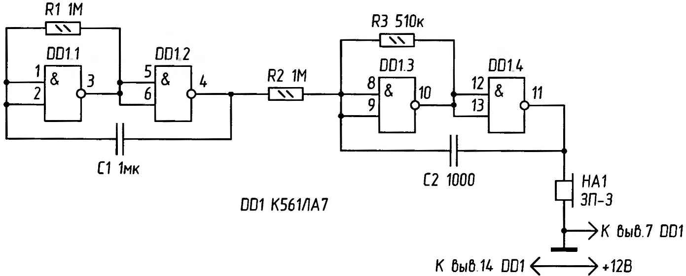
Fig.2. Electric diagram of the generator of sound frequency.
All the resistors and capacitors are advised to use these on the diagram with deviations of no more than 20 % in the first elements (resistors) and 5-10 %— in the second (capacitors). Resistors type MLT of 0.25 or 0.125, capacitors —type MBM, KM, and other with a slight tolerance influence of the ambient temperature on their capacity.
The resistor R1 nominal value Mω 1 —variable linear characteristics of the resistance changes.
If you want to stay on any one any effect, such as “cackling geese” — you should achieve this effect very slow rotation of the engine , then disconnect the power supply and desoldering a variable resistor from the circuit and measure its resistance, to install a permanent resistor of the same value.
At the correct installation and serviceable details the device starts to work (making sounds) at once.
In this embodiment, the sound effects (frequency and interaction of generators) depend on the supply voltage. When the supply voltage increases above 5 V for safety input of the first element DD1.1, you need to connect to a conductor break between the upper scheme contact R1 and the positive pole of the power supply limiting resistor of 50 — 80 ohms.
The device I have in the house is used for games with Pets, training dogs.
Figure 2 shows a diagram of oscillator variable audio frequency (AF).
The AF generator is implemented in logic elements of microcircuits K561LA7. On the first two elements assembled low frequency oscillator. He controls the oscillation frequency of the high frequency generator on the elements DD1.3 and DD1.4. From this it turns out that the circuit operates on two frequencies alternately. Hearing mixed vibrations are perceived as “trill”.
Sound emitter is a piezoelectric capsule SN x (SN-2, SN-W, SN-18 or similar) or high impedance telephone earpiece with coil resistance 1600 Ohms.
Property efficiency CMOS chip К561 series in a wide range of supply voltages used in the sound scheme in figure 3.
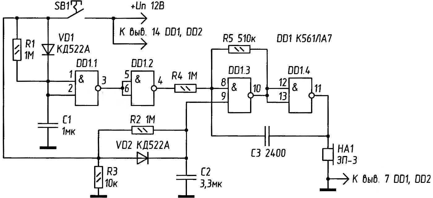
Fig.3. Electric circuit self-oscillating generator.
Self-oscillating generator on the chip K561J1A7 (logic elements DD1.1 and DD1.2—Fig.). Gets the supply voltage from the control circuit (Fig. 36), consisting of RC-charging chain and source follower field-effect transistor VT1.
When the button SB1 capacitor circuit of the transistor gate is quickly charged and then slowly discharged. A source follower has a very high resistance and work the charging circuit has almost no effect. The output VT1 is “repeated” input voltage and current sufficient to power the components of the chip.
The output of the generator (the connection point with a sound emitter) are formed oscillations with decreasing amplitude until the power supply voltage will not become less than acceptable (+3 for chip series К561). After that, vibrations break. The oscillation frequency is selected to approximately 800 Hz. It depends and can be adjusted by the capacitor C1. When submitting the AF output signal to the sound emitter or amplifier, you can hear the sounds of “meowing cat”.
The scheme presented in figure 4, allows to reproduce the sounds of a cuckoo.
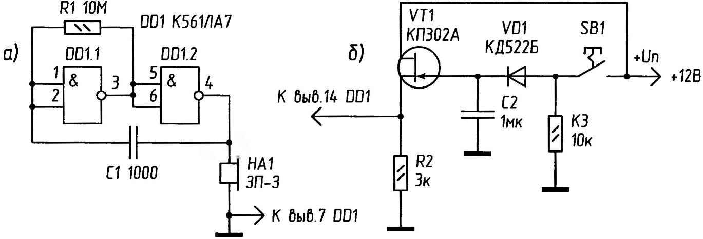
Fig. 4. Electric circuit device with the imitation of “cuckoo”.
When pressing the button S1, capacitors C1 and C2 are quickly charged (C1 through the diode VD1) to the supply voltage. The discharge time constant for C1 of about 1 for S2— 2. the discharge Voltage of C1 on two inverters of the chip DD1 is converted into a rectangular pulse lasting about 1 s, which through a resistor R4 modulates the frequency of the oscillator on the chip DD2 and one inverter IC DD1. During the duration of the pulse oscillator frequency will be 400 Hz to 500 Hz, in the absence of the approximately 300 Hz.
The discharge voltage of C2 is fed to the input element And (DD2) and allows the generator within 2 s. as a result, the output of the circuit is obtained dual-frequency pulse.
Schemes find application in home appliances to attract the attention of creative sound indication of what is happening to electronic processes.
Recommend to read
 Wardrobe? Sliding-door!
A built-in wardrobe is good already because it takes at least half as much material to make as a conventional carcass unit, yet it holds far more, since it is usually made full height from... THE NOVELTY OF THE ICE SEASON
Is it possible sensationalism in modern automodelisme? Honestly, the boys of our group were sure that no. It seemed to them that has long been found-perenity all the design options and...
