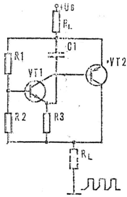
 This device whose description was published in the journal “Funkamateur” (GDR), used in various measuring devices or equipment, where necessary intermittent light or sound alarm. Moreover, the load can be connected both with the positive and the negative pole of the power source.
In the moment of switching on the capacitor C1 (Fig. 1) is discharged. The voltage at the emitter of the transistor VT1 is greater in magnitude than at the base. In the process of charging C1, the potential on the emitter VT1 decreases and when it becomes lower than the potential of the base is approximately 0.6 V, the transistor will open, causing the unlocking of a semiconductor triode VT2. Through it flows a current dependent on the load. The capacitor C1 is discharged through VT1, VT2 and RZ. After his discharge transistors are locked and the process repeats. The frequency of the oscillations determine the values of C1 and RZ. By changing the resistance RZ varies the ratio of the duration of on to off in the range of from 1:1 to 1:100.
Figure 2 shows the scheme is simple and reliable in operation of the alarm device with the use of LEDs or incandescent lamps with currents up to 100 mA. Using a resistor R4 to slightly change the lighting time, but the resistance should not be too large, otherwise the transistor VT2 is fully unlocked. The values of capacitor C1 and resistor RZ can also be changed within narrow limits.

As VT1 can be applied to any transistor series КТЗ15 with gain h219> 50, VT2 — semiconductor triode МП42 with any alphabetic index.
The switch diagram is shown in figure 3, can serve as a turn indicator, for example on a moped. Transistors VT2 and VТЗ respectively types МП42 and П216, П217 any alphabetic indexes and VТЗ not need to be installed on the radiator. Requirements VT1 are the same as in the previous scheme.


