FROM “USELESS” – IN THE RIGHT

FROM 
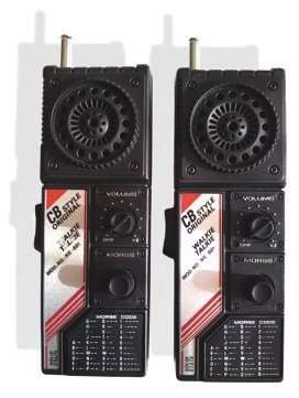
Want to lead a conversation about “retraining” relatively useless or obsolete electronic devices in the useful and necessary. A lot of stuff gathering dust “in the bins” radio Amateur may get a second life. This is especially true in economically crisis periods, and not only the world but also a family. For example, a portable radio (transceiver) citizen’s band (CB), shown in the photo, are unlikely to even be interested in Amateur radio.

The transceiver consists of a generator and amplifier of low frequency (LF), as well as sender and receiver node with carrier frequency 26, 9 MHz. In different variants of this type of transceivers installed quartz can vary in frequency, and the transistors have the names С9013. The high-pass part is performed on the transistor VT1, two-stage ULF — VT2 and VT3; this amplifier is the most important element of the design discharge the battery.
 
When placed close to the transmitter and receiver of one set is impossible to determine the frequency; in some instances the care of the operating frequency from the nominal value up to 2 MHz. On the setting of the frequency — tuned coil core circuit. However, when adjusting the contour of a conventional metal screwdriver inevitable additional error due to the changed terminal screwdriver field in the circuit. The adjustment process required a set of non-conductive material. Therefore, in such a relatively simple design, which is similar to many radio stations walkie-talkie, in my opinion, it makes no sense to achieve the maximum matching frequency between the transmitter and receiver. I guess it meant and manufacturers of the device. Given the low power transceiver, with a precise setting of the carrier frequencies will be able to increase the range of communication for a couple of hundred meters, and in urban areas — and less.
For effective practical application of the “toys” in the home of Amateur radio I have a number of ideas. For example, to change the transceiver in the beacon, a remote alarm on the radio on the alarm is triggered (door open outbuildings, bath, wells, barn, garage).
 
Appearance of the station ST NS-881
 
Appearance radio station ST NS-881
 
View to the transceiver after completion
 
A view of the transceiver after completion
 
The second option is similar to the use of the alarm button, which is constantly in the pocket of the driver-trucker — after all, they often use communication in civil band. It does not require any special skills, permits the’nadzora, and is only necessary registrations directly to the radio output power of more than 1W. If necessary, the truck driver can notify a colleague about a disturbing situation.
 
There are all sorts of other practical applications NS-881; it’s better than just “dusting” it in the bins. For myself, I did just beacon associated with the motion sensor, which by means of contacts of the actuating relay supplies power to the transceiver. But in the process, there were two difficulties, which, however, easily disposable.
 
The first difficulty: the selection of the frequency channel.
 
First, the TRX is “programmed” to transmit a signal at a frequency of 26.9 MHz. Neither the European grid frequency in the citizen band (frequency channel ends at 5), neither domestic not correspond to this frequency. The nearest channel 1C on the European grid (26,965 MHz). European channels C2—C45, D1—D40 approved for use in Russia.
 
Even if you close the switch “to transfer” and set the jumper on the button of the Morse code (that worked constantly sound generator), a signal of this beacon can only take the same “toy” transceiver. And if not, or you want the alert to the more common frequency? Have desoldering a quartz resonator and instead set a different, based on the information in the table.
 
Since the vast majority of users have transceivers with the European grid of frequencies (since it produces even domestic transceivers TAIS), it is reasonable to set such a quartz crystal resonator, which is better suited to your “professional” transceiver, if one is available (for example, other models of portable radio: “the Veda of the world Cup” — 27,1875 MHz, “Ural-R” — 27,175 MHz Pilot — channels C38 and D5 corresponding to the frequencies and 27,465 27,385 MHz). Can be other options.
After installing a new quartz resonator and fixing mode switch “reception — transmission”, as well as installing a permanent jumper on the button of the sound generating a modified transceiver NS-881 looks like photo 2.
 
Now, with the power to “toy” that ceased to be such after the modification, we have a full beacon, is very useful in agriculture for remote alert and warning owners about these or other events that occur at a distance of 1 km from the house.
 
A second complication power save. The “regular” power unit — battery type “Krona” provides a long work of the newly created beacon. Therefore, if the situation allows, I recommend instead to use a more powerful battery, for example D10-D12 with a capacity of 1.2 Ah and a voltage of 12 V To the transceiver voltage is not dangerous. To further reduce power consumption, I recommend to replace the stock amplifier for the WOOFER is shown below.
 
The matching frequency of the quartz resonator output frequency transceiver NS-881
 
The correspondence of the frequency of the quartz resonator output frequency transceiver NS-881
 
 
The fact that most developments bass amps used transistors, integrated circuits К174ХА10, К174УН4 (and others). As a result, even in “quiet” mode at no input signal current consumption is large enough. The amplifier diagram is shown in the figure, has low distortion and quiescent current is only 700 mA. Therefore, it is recommend to use NS-881 (and in similar small radio stations and radios, and other devices requiring amplification of weak signal in conjunction with the economical power).
 
The amplifier works in the frequency range 200 — 6000 Hz non-uniformity of 3 dB. The output power at a supply voltage of 9 V is 0.3 W BA1 to the load impedance of 8 Ohms.
 
In the scheme applied economical Micropower operational amplifier (op-amp) К140УД12. To amplify the small output current of the OU is applied push-pull voltage follower with high gain capacity (CUM) on four transistors VТЗ—VТ6. Circuit R11, C6 prevents the self-excitation of the amplifier at high frequencies. Coefficient voltage gain (KUN) is determined by the ratio of resistances of resistors R7 and R6. The cascade on transistors VT1 and VT2 is used to ensure work OU when powered from a unipolar source. The failure of conventional resistive amplifier allows to avoid excitation of the amplifier at low frequencies.
About the details. The amplifier used small imported resistors with a power dissipation of 0.06 watts. You can use resistors for surface mounting. Electrolytic condensers — K50-35, the rest of KT, KM-5, KM-6. As VT1, VТЗ quite suitable transistors series КТ3102, КТ3130, КГ6111, КТ342 with any alphabetic index. As UT2 and UT4 — any of the series КТ3107, КТ6117. These transistors should have a current transfer ratio base not less than 200 mA. Instead of the transistor VT5 quite fit any of a series КТ6115, КТ6112, КТ668, КТ685. Transistor VT6 — КТ6114, КТ6117, КТ645, КТ680, КТ683. Chip К140УД12 can be replaced КР140УД1208 (the Pinout is the same). As BA1 instead of “regular” dynamic head from portable radio, CB range NS-881 I used 0,5-GDS-2.
 
The establishment. Resistor volume control R3 reduce the input level to zero. Further, selection of the resistance R1 sets the voltage at the emitter VT1 and VT2, equal to half the supply voltage. The selection of the resistance R5 need to set the quiescent current of the amplifier is equal to 700 mA. The engine variable resistor R3 must be in the down (on) position, and the dynamic head at the time of the current measurement it is better to disable (in order to exclude the error from the leakage current C7). Voltage gain is adjustable by selection of the resistor R6.
 
Schematic diagram of amplifier
 
Electrical amplifier circuit
 
Ready amplifier it is advisable to check with generator and oscilloscope. With proper arrangement of the elements of the excitation RF does not occur.
 
Connection and application. The input of the amplifier is connected to the middle output of the variable resistor RP1 (the marking on the PCB NS-881) volume control of the radio station.
 
The use of this amplifier in the NS-881 significantly increased the battery life. Alternative to the described amplifier can be imported uzch integral with the mode of reduction of power consumption. But such a regime cannot be exploited without considerable refinement of the detector receiving tract, making the whole venture unprofitable at the time.
 
A. KASHKAROV, St. Petersburg

Recommend to read

  • THE TUBE IS IN THE ROLE OF THE GRAVERTHE TUBE IS IN THE ROLE OF THE GRAVER
    Furniture, decorated with different shaped pads, looks nice. But to run any profile requires a special tool. The simplest may be a conventional steel tube with a razor-sharp edge. If...
  • POWER SUPPLY WITH ACTIVE FILTERSPOWER SUPPLY WITH ACTIVE FILTERS
    For portable electronic equipment need a small volume and weight of the power supply. To solve this problem relatively simply by replacing passive LC and active RC filters.   The...