
 A commercially available power supply units are Chinese — made adapters have several advantages: they have an attractive modern design; dimensions distinguished by compactness; the scheme includes step adjustment of the output voltage based on the “razgovornoy” load; it is also important that there are acceptable for many price. However, they are not without, unfortunately, and specific disadvantage: during operation, they are “kicking”. Annoying piercing buzz with twice the mains frequency, particularly when using paired with a player or radio.
The reason for the appearance of the background in a very simplified diagram of the filter voltage after the diode bridge, where everything is reduced, in fact, to install one electrolytic capacitor is small (by today’s times) capacitance: 470 UF.
My suggested revision of import adapters aimed to reduce the ripple of the rectified voltage. The cost here is minimal, additional radio equipment could be placed in the body of the unit.
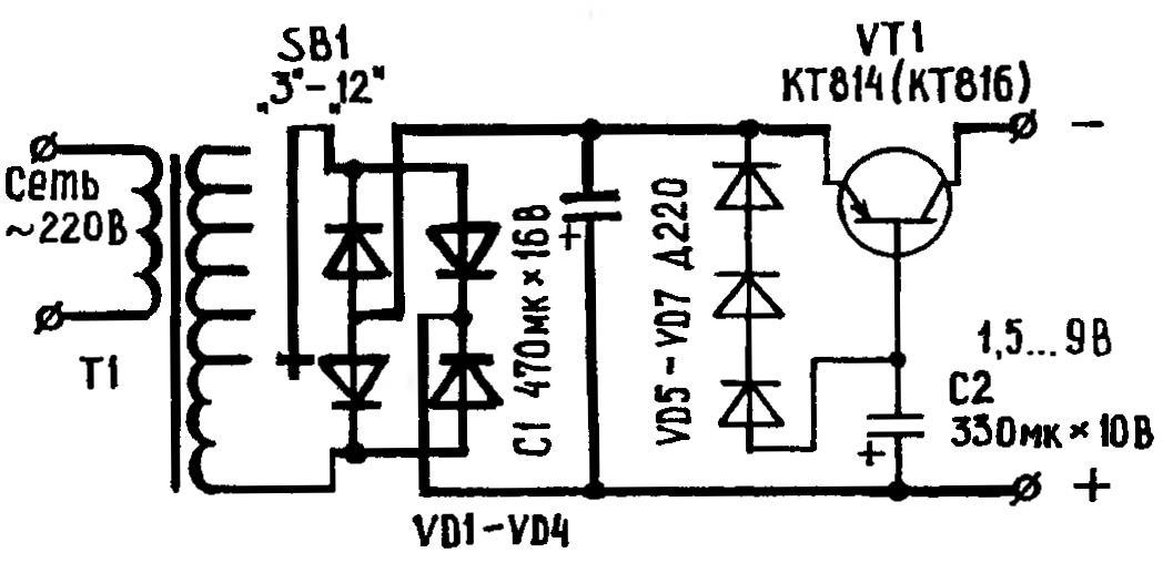
Small improvements (innovations are conditionally depicted by thin lines) and imported power supply is not “fonit”
The scheme improved the unit does not require special explanation. The transistor for a more comfortable working it with regard to temperature, it is desirable to set a small radiator made of tin.
Switch SB1 and once finalized, will give the former voltage level, but the output of the unit they will be a match reduced by 1.5 In (but almost devoid of background) values. At desire it is possible to resolder the wires to the appropriate SB1, and to restore the former identity of the engraved numbers in the switch and the actual thresholds of the output voltage. However, with the upper limit (12 V) then you have to leave.
O. KLEVTSOV, Dnepropetrovsk
Recommend to read
 AND PACKAGING — IN THE CASE
Just a sharp knife needed to turn an empty plastic shampoo bottle, washing tools, preparation of household chemicals in a number of useful things: a ring with a small eyelet can be used... SEAMS TWINS
Brick masonry is always exposed. Brick has a regular geometric shape, and on the background of the uneven mortar joints are very visible and look ugly. To withstand the same thickness of...
