 As you know, galvanic elements, batteries, accumulators and many generators do not have high-efficient, fast trigger protection against short circuits (a short circuit). No its in most sources of the secondary power supply Fuse the fuse, there is not in the bill. First, because the response time, is often absolutely not suitable for modern equipment, instantly reacting to abnormal situations. Second, fuses are one-time protection devices, requiring replacement by a new after his burnout, not everywhere and not always acceptable.
I have designed a device that plugs in between the power source and the consumer, not only protects against short circuit the power supply circuit is a constant current, but also allows you to quickly recover it after short circuit elimination.
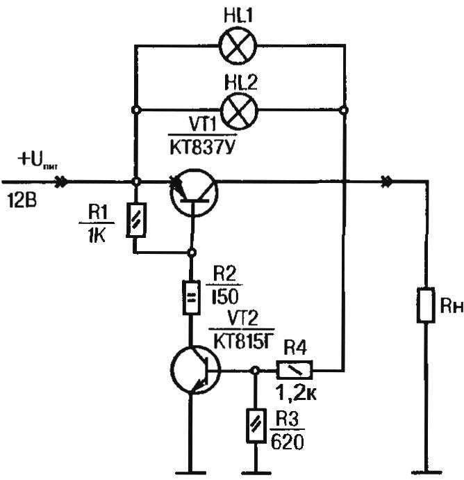
A circuit diagram of the device (see Fig.) pretty simple. It consists only of a chain run-indication formed by parallel (for reliability) incandescent lamps HL1 and HL2, Yes the switch is made on transistors VT1, VT2.
When the supply voltage formed by the circuit:”+” source, the “parallel” of HL1 and HL2, load resistance RL, a “shared” bus. At the initial moment of the filament lamps are not heated and their resistance is small, resulting in open semiconductor triode VT2 (the base current set by resistor R1), and then the transistor VT1.
If the output of the device short circuit, VT1 is necessarily in a state of saturation, shunts HL and HL2. Therefore, the lamp is not lit.
The situation changes drastically when the output short-circuit suddenly occurs. The resistor R4 is connected to the “common” tyre, which causes the immediate transfer of semiconductor triode VT2 is closed. Is also closed and the transistor VT1, while disconnecting the power supply from the emergency phase electrical circuit. The supply voltage is completely applied to HL with HL2, the LEDs of an emergency.

A circuit diagram and a printed circuit Board, a homemade device for emergency light indication and protection against short circuits in a DC circuit.
After elimination of short run easy resume: a disconnect followed by re-connection to the device power supply, which should provide (in accordance with the values of resistors shown in the circuit diagram) the required 12 V input electronic protection. Then directly at the load will be at least 11.5 V. This — the normal mode when the operating current of the device is 2 A, and the voltage drop across it is less than 0.5 V.
With the emergence of the familiar overcurrent in the power circuit in question the device varies somewhat. In particular, a semiconductor triode VT2 only pozakryvali, the transistor VT1 leaves the saturation, and lamps HL1 and HL2 start to glow only dimly. For such a nonstandard mode, typical of 5-volt voltage drop across the protection device with a load current of 3 A. With the further increase of the current load of a semiconductor triode VT2 is closed completely, and the transistor VT1 is in the saturation state up to 15 watts. For reliability of operation of the device the transistor is preferably (but not necessarily — on the signal lamp glow dimly to prevent overheating VT1, disabling voltage) to provide a massive heat sink.
The device is recommended to be mounted on a printed circuit Board with subsequent placement in the body 50x35x20 mm. the Transistor VT1 in the author’s version of a security device attached to the heat sink, being simultaneously the top cover. Lamps HL1 and HL2 are installed in the threaded holes of the same heat sink.
O. SYDOROVYCH, Lviv, Ukraine


