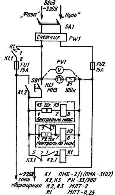
Circuit diagram of automatic relay protection room network against voltage fluctuations in power lines
Before assembling the circuit, both relays RN-53/200 undergo some tweaking. They removed the wires from terminals 4 to the rectifier bridges, and between the terminals 2 and 4 are installed resistors. A typical electromagnetic actuator is converted into a low-noise switching device, which are thoroughly cleaned and adjusted to each other adjacent the ends of the yoke fixed portion of the fixed contactor to the Board not directly, but through the cushioning (e.g., foam) gasket.
Assembling of the machine mounted. The wire used is preferably copper (although not ruled out aluminium) sections 1.5—2.5 mm2 (based on the nominal operating current in the network).
Of course, this takes into account the rules of electrical and fire safety. The circuit Board on the shield is set higher, near the flow meter and electricity fuse to further completely prevent accidental touching of the parts of the machine.
Working properly mounted protective system, no complaints from users does not usually cause. The glow of neon bulbs (and the more different from zero the voltmeter) is judged on the presence of the input voltage at the housing network and make a conclusion about whether or not to include their domestic burden.
If the button is pressed БВ1 will be abnormal and contactor K1 will not turn on, and open the additional contacts will not miss the “threat” of electricity in the house. In other cases, ЭВ1 provides the supply voltage (through the normally closed K3.1 relay control “high” and connected due to relay operation control “minimum” of K2.1) the coil of contactor K1. Engaged, the latter closes the power contacts K1.1, submitting a “phase” in the house.
Voltage relay control “high” ideally should be set equal to 242 V. This so-called setpoint. Given the local conditions it is, of course, may be slightly above the recommended value. remaining, however, within reasonable limits. Well, voltage return (“falling off”) relay control “low” preferably appear at the level of 180-200 V.
Then everything has been going as usual. With the increase above the setpoint and relay control “high”, opening the contacts RS. 1 the power circuit of the magnetic starter coil. If the voltage supplied to the input bus suddenly decreases, then there “drops and the” relay control “low”, TH’^ entails the disconnection of K2.1. The end result in both the abnormal voltage de-energized coil K1 of the magnetic starter. So, disconnect power contacts K1.1 and the whole home network will shut down.
The efficiency of the machine is determined by the rate the relay voltage and time “falling off” contactor starter.
V. KARNAUKH, p. tyazhinskiy, Kemerovo region.
Recommend to read
 WHEELBARROW-TRAILER
The new law on compulsory insurance of vehicles in conjunction with the ever increasing prices of gasoline has forced me to give up reliable motorized assistance scooter cargo "the... A RELIABLE “BABY”
We offer mini tractor "baby-3" (the third model) was made by me in the calculation of the mechanized harvesting of hay. From here he and a sufficiently powerful power unit, and two...
 Voltage instability in the regional power lines, unfortunately, are not so rare. Especially during strong winds, when the wires of overhead lines of 0.4 can overlap. Because of the suffering of electro-, radio – and TV equipment, included in the housing network, where the voltage can suddenly become equal, say, 100, or Vice versa, 350 V. However, for my appliances I have five years did not worry, as the anomalous voltage in the network it protects a homemade relay system.
