Automatic device can be used in various models, toys that when meeting with obstacles will change their movement, as well as in everyday life (villages, for example, in the chair the lights went on in the lamp, the music began, earned the fan); to turn the light on in the premises (hallway, room, pantry); for the car alarm.
Previously published schemes of capacitive relay is quite complex, have large dimensions and a high level of interference radiation. Meanwhile this device within a radius of 4-5 m us a picture that is small in size (85X30 mm), powered from a DC source voltage 9-12 V supply current in the initial state to about 7 mA, and the relay — to 45 mA.
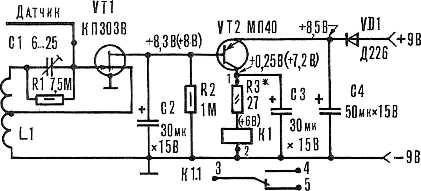
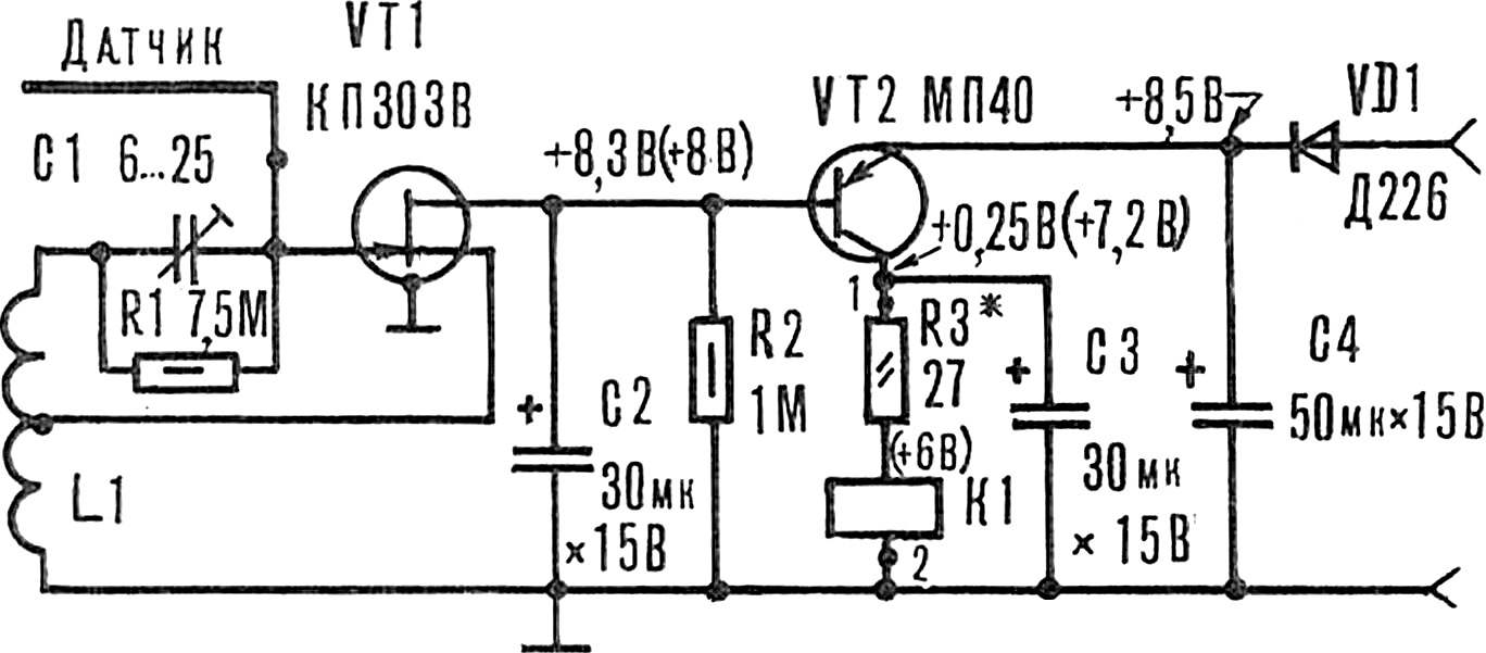
Schematic diagram of the capacitive relay in figure 1. Transistor VT1 is assembled a low-power generator with an operating frequency of 465 kHz, and the triode VT2 electronic key to turn on relay K1, the contact system which connects the actuator. The VD1 diode protects the device from accidental polarity reversal plug-in power supply.
Fig. 1. Schematic diagram of the capacitive relay (in parentheses voltage at the relay).
The range of capacitive relay, that is, its sensitivity depends on the configuration of the capacitor C1 and sensor design, and reaches 50 cm.
The design and details. Capacitive relay is assembled on PCB, made of one-sided foil fiberglass or Micarta size 85X30 mm (Fig. 2). Coil L1 is wound on a polystyrene frame from the contours of DV (long waves) transistor radios or on makeshift frame Ø 7 mm, made of paper or other insulating material (Fig. 3). The distance between the “cheeks” of 1.5—2 mm. the Coil has 1100 turns (550+550) with a tap from the middle of the wire marks PEL or PEV 0,06. Winding in bulk between the “cheeks” of the frame.
Fig. 2. Printed circuit Board device with the layout of the elements.
As the sensor uses the cut insulated wire Ø 1.5—2 mm, a length of from 15 to 100 cm, or a square or a square grid made of wire, with sides of from 15 to 100 cm.
The sensor and circuit Board are in close proximity to each other, and the wire or plane antenna mounted to the ground of the PCB. “Minus” of power supply must be connected to the housing (metal) structures, which will be applied to the capacitive relay.
Resistors, the diode and the coil L1 is mounted on the circuit Board vertically.
Fig. 3. Frame for winding the coil.
The parameters of radioelements used in the device is not critical. Trimmer capacitor — CPC-M, but you can use another type with a range of capacities from 3 to 30 pF. Electrolytic capacitors C2—C4, applied brand K50-6, but you can use other types, just have to modify them under the printed circuit Board. Of the capacitor C2, C3 — 20 to 30, C4 — 50 to 1000 UF.
Diode D226 can be with any alphabetic index. You can also use other solid state device designed for direct current up to 100 mA. Transistors: VT1 — field brand КП303, VT2 bipolar p-n-p type brand MP40 with any alphabetic indexes. Instead of the last, is also suitable series P13, P14, tribe-apparatus P15, R16, МП39, МП41, МП42 with any letter indices, and h213 .
K1 — relay РЭС10 (passport RS4.524.303). Instead, you can connect a small electric motor for toys or sound simulator (“meow”, “cuckoo”, “the Nightingale,” etc.).
The R1 resistor — any type of resistance from 6.8 to 7.5 MW. R2 — 820 ohms to 1.1 Mω. The value of resistor R3 is selected in the range from 0 to 30 Ohms depending on the current the relay or the motor.
Powering the device in stationary conditions is best from the network rectifier 9 V, rated current up to 100 mA. For connection to a power source, grounding, and actuator on a printed circuit Board mounted pins from copper wire Ø 0,8—1 mm and a height of 5-7 mm. For attachment to the PCB has 4 holes Ø 3 mm.
The establishment. Connect to the Board sensor and the DC voltage of 9-12 In the correct orientation. Insulated screwdriver to set the rotor of the capacitor C1 (Fig. 4) in the position of minimum capacitance (6 pF) — this work relays. Then slowly rotate the rotor C1 in the direction of increasing capacity until it is turned off K1 (at setting C1 try to stay as far away from the sensor).
Fig. 4. Tuning capacitor C1.
Bringing the hand to the sensor, test the sensitivity of the capacitive relay until camerabattery (the smaller the capacitance C1, the greater the sensitivity of the device).
V. HERDSMEN, Novorossiysk
Recommend to read BUCKET-IMPROMPTU Magnetic stand made from old magnet, will take care about the safety of various small items — from paper clips and pins to "precisely" small tools and fasteners. It will also help to... CHILDREN’S TWO FLOORS No one would bare to go one size for child and adult. Why children's room should be the same with others! It is, as a rule, the smallest in the apartment, and the furniture in it you... 
 Automatic device can be used in various models, toys that when meeting with obstacles will change their movement, as well as in everyday life (villages, for example, in the chair the lights went on in the lamp, the music began, earned the fan); to turn the light on in the premises (hallway, room, pantry); for the car alarm.