 Before proceeding to describe the proposed design should make an important note. Developed contactless control can be applied not only in computer technology. Described constructive design and purpose of the device is just one example of its possible applications.
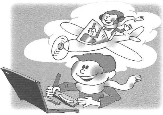
Among fans of aviation history well-deserved popularity of the computer game “Il-2. Forgotten battles” with many additions. No history textbook do not explain the calm courage of the pilot of attack aircraft, precisely as in a laboratory experiment, leading on the combat course is tormented by flak machine. Or the frenzied excitement of the pilot “the Ride”, seeing as growing in his sight silhouette “Boyana”.
However, the position of the virtual pilot is not as convenient as at present. And the picture on the monitor is inferior to reality, and just not enough hands to work with the keyboard. The last problem is partly solved by using the joystick. Here there would be more pedals to control the rudder. However, they are available only in very rare and expensive devices. However, even in the cheapest models there is a third controller that can be used at will either as a pedal, or the Gaza strip. Open your joystick (Fig.1) I found that the extreme conclusions of all variable resistors (potentiometers) are connected in parallel. Obviously, they removed one or another constant voltage which is supplied to the circuit. This was the starting point for development.
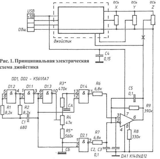
Fig. 1. Schematic diagram of the joystick
The simplest solution obviously is to make the pedals, the axis of which will serve as a variable resistor. They can be part of a simulated control system in any real airplane. But apart from high technical and historical accuracy, this solution has considerable disadvantages. The design is very bulky and heavy. The problem arises with its attachment to the floor. In the hot moment of battle, or when it is required on takeoff to keep from turning the reactive torque of a powerful engine this “beast” as the La 5FN, it is difficult to resist in order not to put pressure on the pedal as it should. Backlash in mechanical assemblies make managing difficult. Brings joy and wear variable resistors.
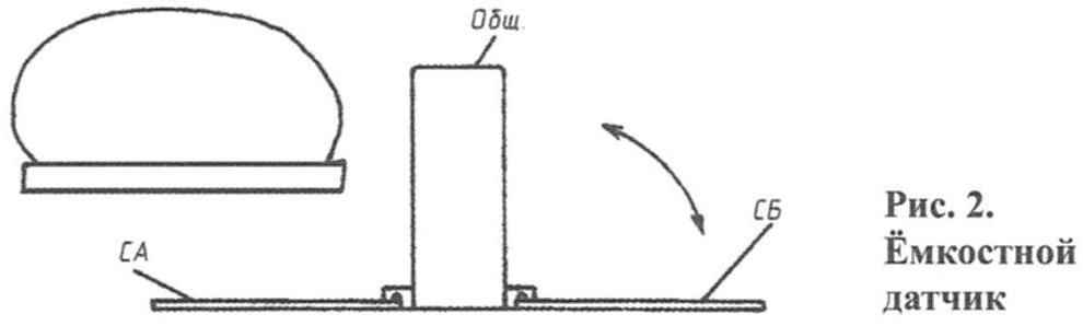
Fig. 2. Capacitive sensor
In short, it requires some other design, though not as historical, but more convenient and compact. And why to us “not to beat” all of these mice, keyboards, touch screens AI-backgrounds, necessarily require direct contact and separate the control process from the surface of the panel, move it to the volume on it? Remember how in one of the McGee novels: “the Stranger ran a hand over the green light. He went out and again lit up brighter than before.” We too can do similar.
The first thing that comes to mind when thinking about non – invasive management is optics. However, most optical systems work on clearance or on interruption of the beam. Insert your hand in some sort of gap between the light source and the receiver? Who needs a “contactless” device? Schema is working on reflection usually deal with a special, contrast printed labels and bar codes. The reliability of their response on the subject, which can be of any color and texture, is also questionable. Limits the freedom of choice of the designer and one more thing – the best optics uses lasers. But their radiation is harmful to the eye and therefore to apply them in the control panel, which is looking man is not desirable. Inevitable in the operation of the pollution and dust contamination of optics from time to time creating problems. Finally, if sensors greater than one, this leads to a significant complication and appreciation of the scheme.
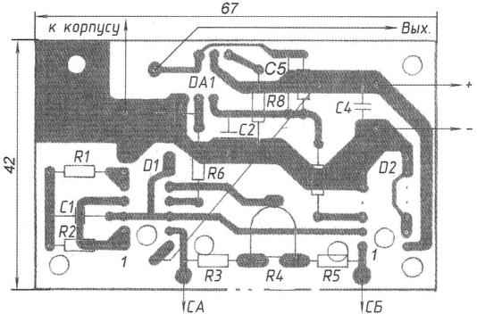
Fig. 3. Circuit Board control unit
So I decided to go the way of using capacitive sensors. The first such systems used resonant circuits and was very unstable. Almost each time had required adjustment. Later appeared more stable digital designs on the principle of pulse delay. However, it was conventional touch device. Their authors apparently did not have enough imagination to imagine the device working without direct touch. I decided to try…
Take a look at figure 1. The generator on the elements 1.2 D, 1.1 D produces pulses on the pulse shaper at the front for D 1.3, D 1.4. At its output (pin 11) there is a logical 1 except the moment after the arrival of the front pulse from the generator output (vyv. 3). At the time of pulse delay in the chain, R4, R3, SA on all inputs D1.4 set the logic 1 and the output is a logical 0. While the capacity of the sensor SA, and hence the duration of the zero pulse is small, the average DC voltage at the output of the shaper, smoothed R6, NW almost does not differ from the logical unit. But is the capacitance of sensor increase as the logical 0 at the output of the shaper takes up most of the period of clock pulses and the output voltage decreases. To obtain the proper sensitivity of the device requires that the pulse duration of the former was comparable with the period of clock pulses (but does not exceed them). This is achievable with the frequency of the clock generator is not below 100 kHz.
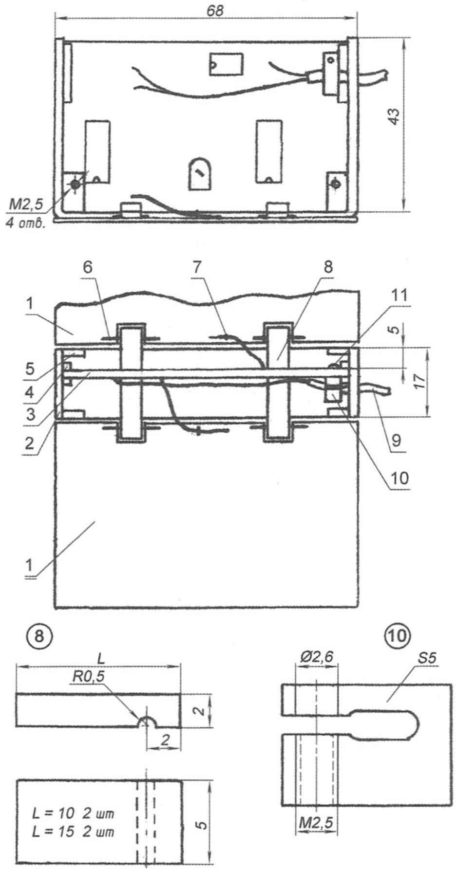
Fig. 4. Contactless pedal:
1 — plate capacitive sensor;
2 — housing;
3 — Board;
4 — guiding circuit Board (4 PCs.);
5 — lug (4 PCs.);
6 — axis;
7 — wire ring (2 PCs.);
8 — panel;
9 — output cable;
10 — fastening collar;
11 — screw M2,5
Now look at the design of the capacitive sensor (Fig.2). It is a horizontally located plate foil fiberglass. The second (ground) electrode is a tin casing-screen, which is placed vertically the device Board. They form somewhat unusual, half-capacitor plates that are perpendicular to each other. He clearly responds by increasing its capacity for premises in its field any object, as the conductive current, and dielectric. The subject is felt at a distance of not less than 30 mm. This design gives a fairly sweeping signal that can overcome interference and instability. As the operational amplifier DA1 can bring its amplitude to any desired value. Move the leg towards the plate and the wheel of Your plane will turn. Keep your foot back up or back and the process will go in reverse order.
Capacitive sensors, just like the pedals in a real aircraft or two. Because the signal from one sensor is opened to the inverting input of the amplifier, and the other at the non-inverting, the output voltage depends on their balance, which leg do you “give” more. The scheme in this case is not very complicated, because the clock generator and even the inverter D1.3 can be shared for multiple channels. Strengthening of Oh is several orders of magnitude for modulating redundant. Change gear ratio control by entering the chain of negative feedback. R9 reduces the gain, and AC OOS even deeper, thanks to the condenser 5. This eliminates the possibility of oscillation.
The printed circuit Board of the device shown in figure 3. In the free from sections of the foil circuit Board in the area of connection of the capacitive sensors is drilled a plurality of holes with a diameter of about 3 mm to reduce the initial capacity and increase the sensitivity of the device. The unused inputs of elements D2, in order to avoid damaging static charges are grounded. These conduits it is desirable to make thin. Then, in case of need (failure of the work items or revisions) you will be able to cut and use these elements.
Design. The plates of the capacitive sensors is positioned with the foil up. They are pivotally fastened, can be lifted and pressed against the walls of the housing, forming a compact box, convenient for carrying and storage. In the area of the cutouts for this soldered axis of scrap copper wire with a diameter of 0.8 mm. Also, the plates are soldered the flexible wire to the circuit (best MGTF) and the wire rings holding the unstripped part and prevent breaking of wires in the place of Stripping. After all the Lunches the working surface of the sensor must be isolated from electrical contact with extraneous objects. In many cases, this is sufficient stickers of wide tape.
The device is a U-shaped clip made of plastic with a thickness of 2 mm. From scraps of plastic cut and glued inside the guide slots and lugs, which are made threaded holes for fastening of a casing of the screen. In cuts of the lower legs of the housing are invested by the axes of the sensor plates and are stuck with overlays, also fixing the lower part of the Board.
U-shaped casing-screen is made of sheet metal. To reduce the initial capacity and the influence of the support surface it does not reach a few millimeters to the bottom of the housing. Opposite the trimmer R4 in the screen the hole. Inside the screen is soldered a flexible wire to connect the common wire to the Board.
The establishment. Install R4 in the middle position. Instead of RZ solder on short wires rigged a resistor of about 1 Mω. Set it to the minimum value. Make sure that podstreshny, its wiring and any other items not got into the field of the sensor SA. Gradually increase the resistance as long as the DC voltage at pin 11 DD1 will not decrease by 20 – 25 %. It is a signal that the device has started to feel the surrounding space. Measure the resistance of podstroechnye and replace it with the same constant resistor, and podstreshny transfer in place of R5 so that it is not included in the field sensor SB. Set the output of the second generator is the same voltage as at the output of the first. The final balance install resistor R4 with a thin dielectric screwdriver after complete Assembly of the device. Remove the screwdriver and check the voltage at the output of op-amp – it should be close to half the supply voltage.
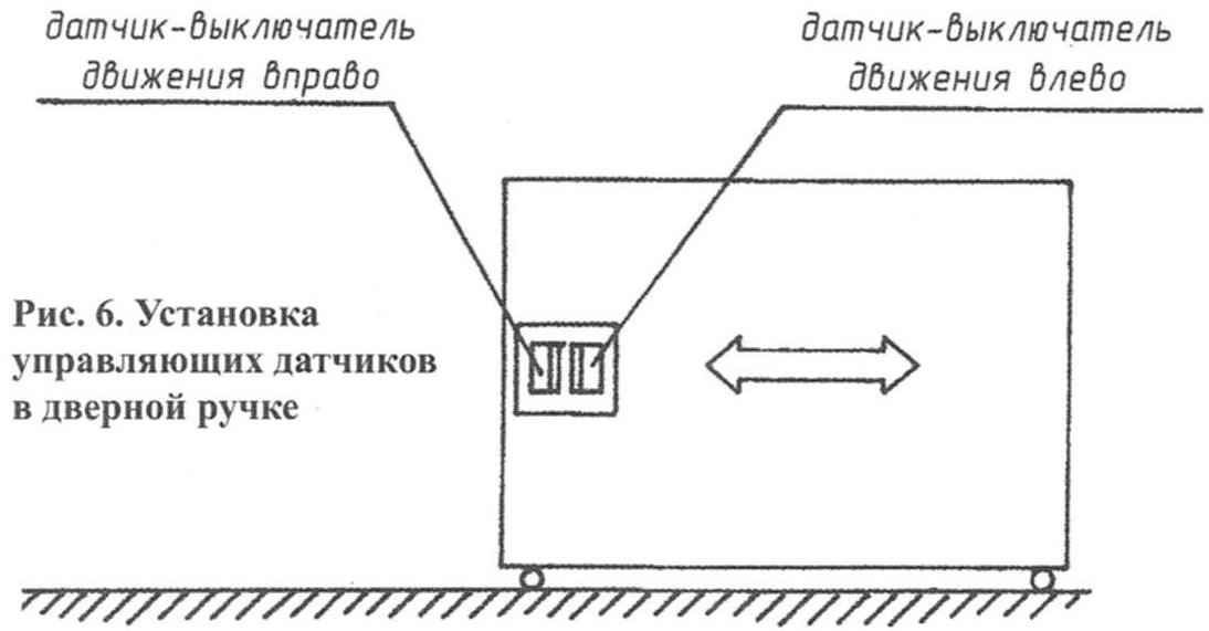
Fig. 6. Installation of control sensors in the door handle
The device was successfully tested with the program “Il-2” and a simulator of glider “Condor”. The degree of realism was very close to this aircraft. However, the aforementioned program was not created for wingless people. Look at the ball “Pioneer” and, after a little practice, everything will be fine.
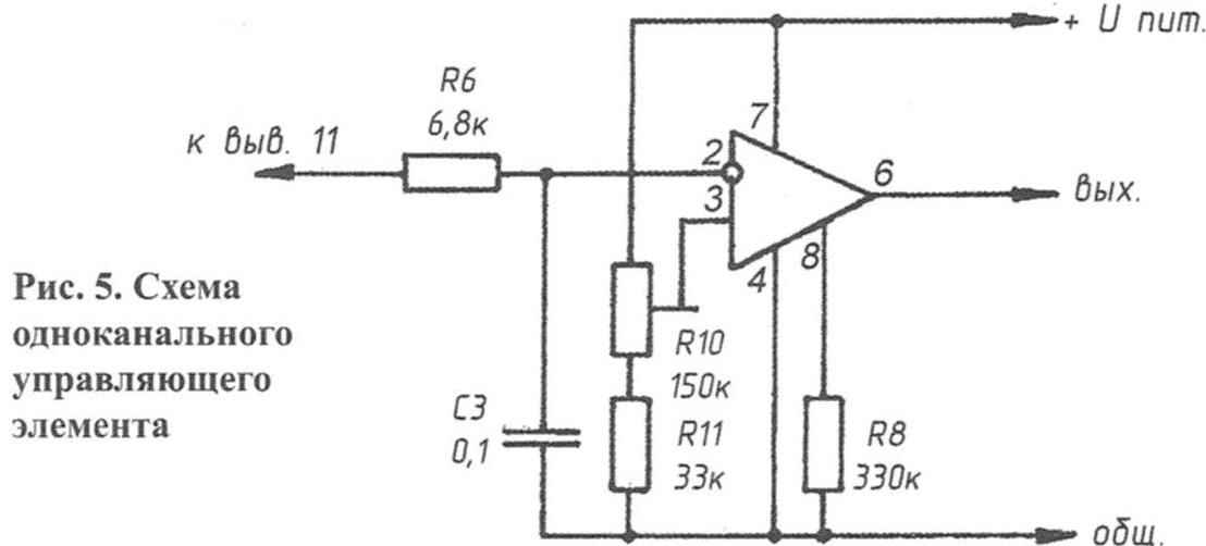
As already mentioned, the proposed non-contact control can be applied not only in computer technology. In most cases there is no need for two-channel balanced scheme similar to the one described. The single element can be made, as shown in figure 5. Since the output of the shaper is connected to the inverting input of op-amp, in the initial state, the output voltage of the device a little. The voltage at the non-inverting input is set by R10 postroeniem just below the switching threshold. If you bring your hand to the capacitive sensor, the voltage at the output will rise. It can be used to control or simply on / off any devices. In the latter case, the chain of OOS is not required. In experiments with the device, this option proved to be quite workable.
Embedding a contactless control in any equipment it should be remembered that the sensor responds to the capacity made objects not only in front, but behind it, that is in the body of the instrument. It is important that this parasitic capacitance was smaller, and most importantly – is unchanged. Non-rigid mounting of the sensor or freely hanging next to him, wires can bring down the setting. It does not allow to realize good sensitivity.
Interestingly the use of contactless controls (two independent channels) for movement of any doors, sashes, etc., by Installing two sensors on the handle, as shown in figure 6, you can “push” the flap in any desired position, without touching it.
Of course, the classic toggle switches and knobs easier and cheaper. But still there are applications where the proposed non-contact control elements are preferred. For example, in hazardous work environments, when absolutely necessary to exclude electrical contact with the equipment, transmission, etc. Thus, many devices in the future will be able to cope with just one flick of the wrist, not armed units, tokens or any other devices.
A. LISOV, Ivanovo
Recommend to read
 DRIED FRUITS AT HOME
brickos — valuable fruit crop originated from Central Asia. However, not all varieties are suitable for drying because of the low content of the substance, the main component of which is... VELOPLIVD WITHOUT “DEAD ZONES”
Improving the efficiency of the drive — a problem which concerned not only the designers of the bikes, but the owners of these cars. Since the invention of the Bicycle pedal drive...
