Portable electronic devices with low-voltage power supply are often designed for batteries and accumulators. Among such devices, the most popular are electromechanical and digital clocks, radio receivers, flashlights, and… wireless doorbells operating on a radio channel at a frequency of 303 MHz (there are variants at 933.25 MHz). Digital cameras with a connector for external power supply of 3.3 V (for example, Olympus C-765), portable CD players, voice recorders, hair clippers, and even mobile phones also belong to such devices. All these devices (their list is not limited to those listed, but much wider) are united by the fact that they are designed to be powered by batteries and accumulators, external power sources with a nominal voltage of 3 V ± 10%. How to provide them with power when the “standard” adapter is lost or faulty?
If the consumption current exceeds 0.3 A, the easiest way to power a low-voltage device from a 220 V network is with a power supply that has an “uninterruptible” function, that is, providing power when there is no voltage in the network. I offer readers a schematic diagram of such a device (Fig. 1).
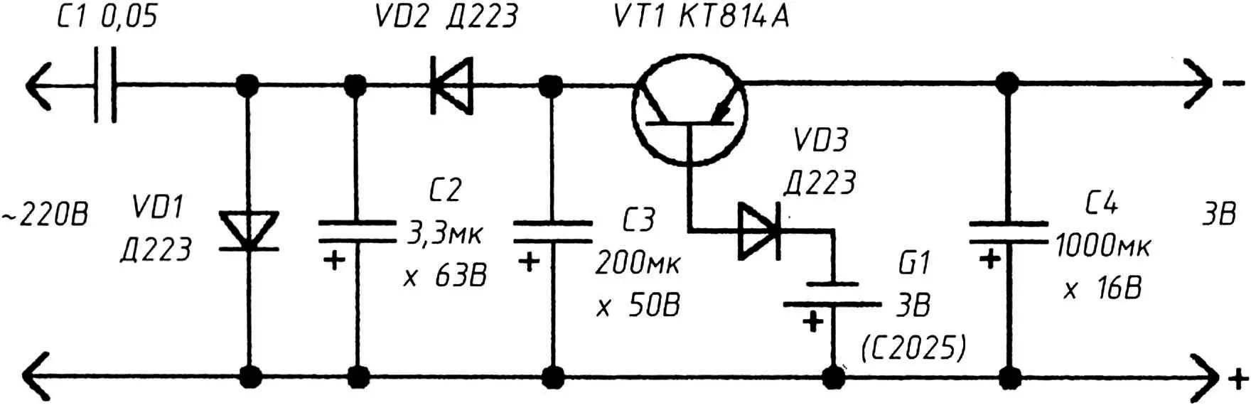
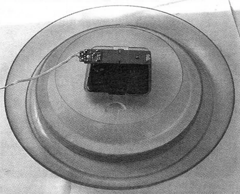
The voltage taken from the divider C1, C2 is rectified by diodes VD1, VD2 and smoothed by the oxide capacitor C3. Without load, the voltage across capacitor C3 does not exceed 14 V. Transistor VT1 is connected in a common-base circuit and its collector-emitter junction is fully open (voltage drop does not exceed 0.5 V) – the voltage across the load (across the plates of the oxide capacitor C4) is 3.3 V. In the absence of mains voltage, current flows through the circuit (with a connected load) through the emitter-base junction of VT1 (the total voltage drop across VD3 does not exceed 0.3 V). And it can be further reduced if diode VD3, which protects the transistor when mains voltage is applied to the device input, is excluded from the circuit. Thus, in autonomous power mode, at least 2.7 V is delivered to the load. This voltage can already power an electromechanical alarm clock or wall clock (photo at the beginning).
About the components
The device does not contain a single resistor and practically does not generate heat, even transistor VT1, since the current flowing through its junction is very small. With the load disconnected, the current could not be measured at all.
All diodes VD1, VD2 can be replaced with КД105В – КД105Г, КД213, Д226 with any letter index. Diode VD3 is preferably used from series Д219, Д220, Д223. Oxide capacitors – type К50-29 or similar. Capacitor C1 is better to use from an unnecessary ballast, converter for a fluorescent (energy-saving) lamp – such capacitors are designed for high reactive power and practically do not generate heat when turned on.
The circuit elements are mounted on a board sized to fit the battery compartment.
The phasing of the connection is not critical. When assembling and connecting the device, care should be taken, as its elements are under the voltage of the 220 V lighting network.
3 V, 0.75 A regulator
High stability of radio-electronic equipment is ensured by the stability of the transfer characteristics of all links, which depend on the stability of the supply voltages. Both exceeding and reducing the operating voltage poses a danger to radio equipment. That is why it is very important to stabilize the voltage of the power supply. A simple way to achieve this goal is to use popular and inexpensive integrated voltage regulators from the КР142, LM78xx series and similar. In this case, the LM7803SR regulator deserves attention, the connection diagram of which is shown in Fig. 2.
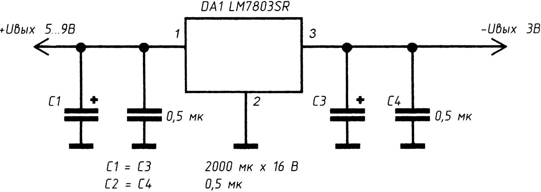
The maximum load current of the regulator is 750 mA, which is quite sufficient for powering low-power loads, examples of which are given above. At a load current of more than 100 mA, the microcircuit should be installed on a heat sink. The input DC voltage for this circuit should be in the range of 5…10 V.
Both circuits do not require adjustment. They can be successfully used in power adapter devices (with an output voltage of 3 V), for example, when the standard adapter is unavailable.
A. KASHKAROV, St. Petersburg
Recommend to read
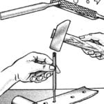 BALL PUNCH
When working with imitation leather or thin skin, which are often used for the models or devices, there is a need in the holes of small diameters. In these cases, rescue of a homemade... Su-25
Su-25
Dvuhdverny aircraft-su-25 attack aircraft designed for direct support of troops in local conflicts under conditions of strong counteraction of the enemy air defenses. The development the...
