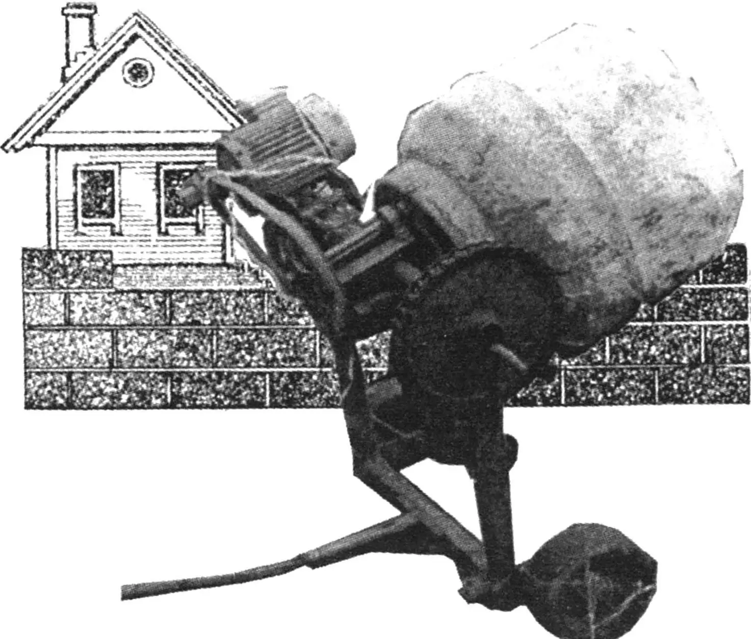
A concrete mixer is constantly needed when building a house. A lot of cement mortar is required, and it also needs periodic mixing. A tub with a shovel are poor helpers here — you’ll tire yourself out to the point of aching all over, and the mix quality will still be low. Buying a branded, expensive unit is beyond many people’s means.
So the only option is to build a mechanical concrete mixer yourself. For example, a mobile one with an electric drive for thorough mixing of cement mortar ingredients and a tilting mechanism to make loading and unloading easier. Use a 250-litre metal barrel with welded blades as the mixing drum.
Working out the kinematic layout of such a machine was no great effort for me — a former aviation technician. A scrapyard helped bring it to life, where parts from decommissioned farm machinery were rusting away.
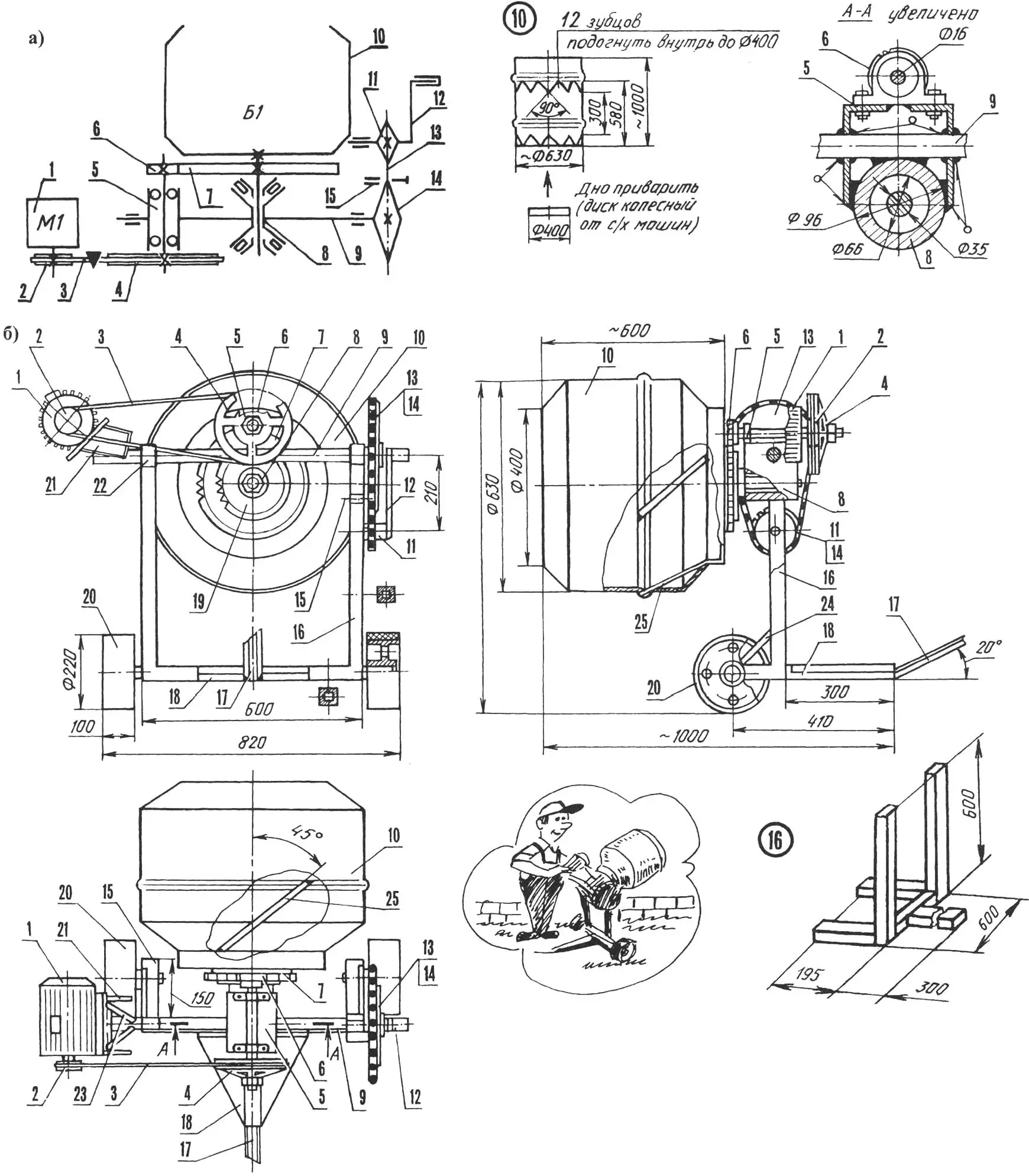
1 — induction motor (220 V, 1.2 kW, 900 rpm); 2 — drive pulley (D = 58 mm); 3 — V-belt; 4 — driven pulley (from ZIL-130 truck compressor, D = 222); 5 — intermediate shaft assembly; 6 — drive gear (z = 9); 7 — driven gear (welded flywheel ring from GAZ-51 or Moskvich car, z = 116); 8 — main shaft assembly; 9 — tilting mechanism shaft (steel tube 40×6, L800); 10 — drum (from 250-litre iron barrel and steel wheel disc from farm machinery); 11 — tilting mechanism drive sprocket (z = 11, t = 25.4); 12 — homemade handle; 13 — roller chain PR-25, 4; 14 — tilting mechanism driven sprocket (z = 36, t = 25.4); 15 — lock (welded steel tube 28×5, L64 with steel pin Ø18, L80); 16 — frame (steel tube 45x45x4); 17 — drawbar (hex 42, L1000); 18 — gusset (2 pcs.); 19 — disc-hub (sprocket z = 25, t = 25.4); 20 — rubber-tyred wheel (2 pcs.); 21 — motor subframe assembly; 22 — tilting mechanism bearing (welded steel tube 45×5, L46, 2 pcs.); 23 — strut — phase-shift capacitor mount (steel rod Ø10, 2 pcs.); 24 — strut (steel rod Ø15, 2 pcs.); 25 — welded blade (steel plate 250x16x8, 4 pcs.). Parts 2,3,6,11,13,14,19,20 — from decommissioned farm machinery
Welding was no problem — a homemade welder came in handy. With lathe work, try as I might to keep it to a minimum, things were trickier. Of course I did the small bits myself with a grinder, drill and hand tools. Turning the main shaft and bearing seats had to be left to a turner at a nearby machine shop.
I built the mixer drum in several stages. First I cut a blank from the barrel with toothed edges, bent them inward to 400 mm diameter and welded the joints. For the bottom I welded on a wheel disc from scrapped farm machinery. I patched the unwanted holes. Then I welded on the toothed flywheel ring from a GAZ-51 engine and (strictly centred!) the main shaft, reinforced with a disc-hub. I fitted the end of the latter to a 7307 tapered roller bearing. I also added four welded blades from 8 mm steel plate.
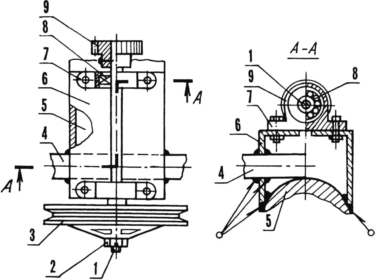
1 — intermediate shaft (steel rod Ø16); 2 — castle nut M16; 3 — pulley (from ZIL-130 truck compressor, D = 222); 4 — tilting mechanism shaft; 5 — main shaft bushing; 6 — welded base (steel angle 40×45, L180, 2 pcs.); 7 — bearing housing (from farm machinery, 2 pcs.); 8 — bearing 180502 (2 pcs.); 9 — gear (z = 9)
To match the drum dimensions I welded a frame from square steel tube sections. The result was a two-post design with a fork base. Into the front projections, reinforced with struts of 15 mm steel rod, I welded bushings (not shown in the drawing) for the wheel axles. I attached the drawbar to the heel at 20° to the horizontal — a one-metre length of 45 mm hex bar. I added gussets to strengthen the assembly.
I fixed the tilting mechanism bearings to the posts by electric welding. In the right-hand post I drilled a hole and welded in the drive sprocket shaft with a homemade L-shaped handle. Later I also fitted the lock bushing on that post. The connection is welded, at the position of the driven sprocket mounted on the tilting mechanism shaft.
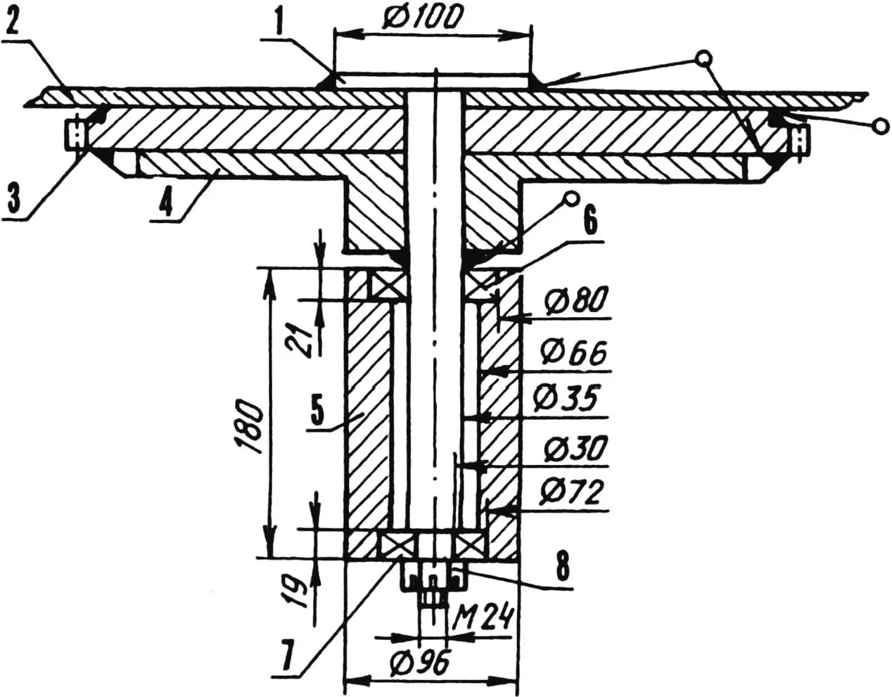
1 — shaft (steel 45); 2 — drum; 3 — gear (toothed flywheel ring from GAZ-51 or Moskvich car, z = 116); 4 — disc-hub, welded (sprocket z = 25, t = 25.4); 5 — welded bushing — tapered roller bearing housing (St3 or steel tube 96×15, L180); 6 — bearing 7307; 7 — bearing 7306; 8 — castle nut M24
At the other end of the tilting mechanism shaft is a three-phase induction motor (1.2 kW, 900 rpm). It can be run from 220 V mains through a capacitor bank of 40–80 µF total (there is a mount formed by two struts with the welded bushing and motor subframe cheeks), as in circuits repeatedly published in «Modelist-Konstruktor» magazine (No. 8’95, 8’99, 10’2000).
Torque from the motor goes via a V-belt drive to the intermediate shaft, whose bearing housings are fixed to an angle-iron base. That base is welded both to the tilting assembly shaft and to the bushing that forms the main shaft roller bearing housing. In effect it’s a single tilting unit, described (for clarity) as three separate assemblies.
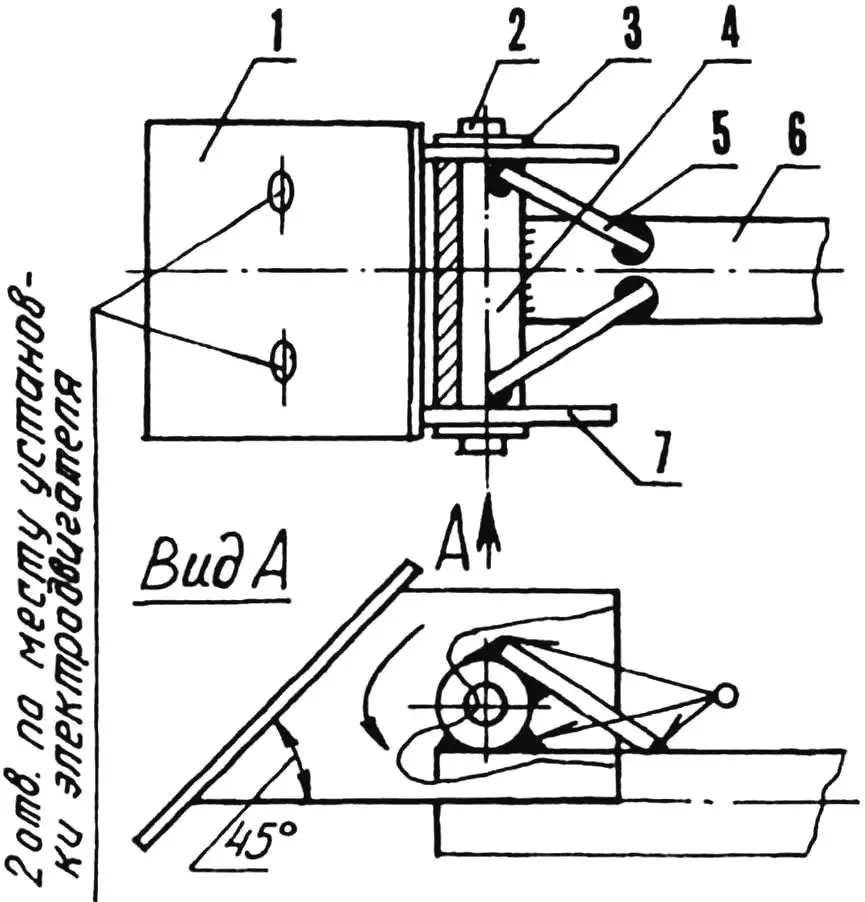
1 — motor mounting plate (steel plate 125x84x4); 2 — pin (steel rod Ø18, L130) 3 — cotter-pinned washer (2 pcs.); 4 — welded bushing (steel tube 28×5, L90); 5 — strut — phase-shift capacitor mount (steel rod Ø10, 2 pcs.); 6 — tilting mechanism shaft; 7 — cheek (steel plate 200x100x3, 2 pcs.)
Each of them has a functional shaft with its own pair of bearings. The tilting assembly uses plain bearings — a tube rotating in bushings; the intermediate shaft has ball bearings, the main shaft roller bearings. The latter are needed to take the considerable axial loads during drum loading and unloading.
Other successful features of this concrete mixer include smooth running, structural reliability and stability, and no risk of tipping when the frame heel is on the ground. And of course the belt tensioning idea: the motor’s weight pulls down the subframe and keeps the V-belt from slipping.
Once neighbours saw the advantages of my concrete mixer compared even to commercial ones, they often ask to borrow it for a day or two. Demand is especially high in summer, during the building season.
«Modelist-Konstruktor» No. 12’2000, K. PANASYUK
Recommend to read
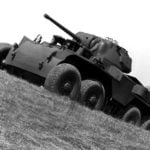 ARMORED VEHICLES OF THE U.S. ARMY
The history of American wheeled armored vehicles rather unusual and in many ways instructive. Geopolitical position of the country protected it from land invasions. At the same time... STRUG
STRUG
The knives or Strug indispensable when machining curved surfaces. To make them simply — it will only have an old file with a length of about 200 mm. In the first file you need to...
