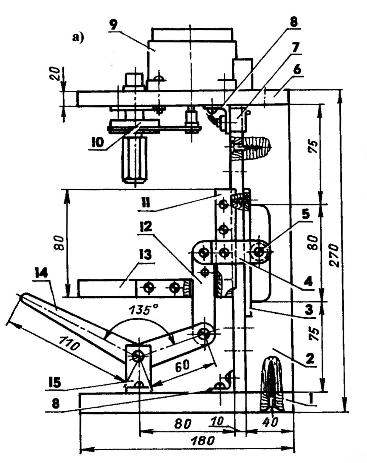
Bracket connecting rod pivotally connected with the lever lifting mechanism of the table. The lever is mounted on the axis of the support, which is rigidly attached to the base. All axis — M4 screws with a thread only at the end. The connecting rod is made of steel sheet 2 mm thick in its lower hole tapped M4, which when connected with a lever screwed the axle bolt and lock nut. Support with lever matched ready, but they are easy to produce and push a lever from the same material as the rod, the prop — of the pair of segments dural area is 40×40 mm, slightly shortening the lower shelf, and as the axis to use, as in other connections, the bolt M4.
Due to the fact that the linkage provides a relatively small vertical travel of working table, the machine design provides two working positions of the table: with top location of the site relative to the slide, or from the bottom. For installation in the lower position the platform along a symmetry axis about the slide made the cut 20×3 mm for the passage of the connecting rod. To install the pad in the third, intermediate position in the connecting rod made an extra hole for the axle bracket.
Spindle Assembly of the second variant of the layout of the mini-lathe:
1 — collet Chuck (brass LS59); 2 — a clamping nut (steel 20); 3 — driven pulley (aluminum); 4 — bearing housing; 5 — bearings 27; 6 — Bush (aluminium) 7 — the console (plywood s20)
circuit of the motor RD-09
Circuit of the motor KD-25
While working on stanochek I use two options for spindle Assembly. In the first embodiment, when it is required to drill small holes with a diameter of 1.0—1.5 mm, for clamping drills use a homemade collet made of brass stamps LS59. In contrast to conventional devices in which the clamping sleeve is usually divided into three sectors, cut my four. Technologically, it’s much simpler: it is necessary to drill the axial bore and two mutually indicate instead cutting strictly along the axis. Operation is best performed on a horizontal milling machine, but you can cut and hand — slizovskiy.
The rotation of the spindle with the collet is given by RD-09 via the lower belt drive with pulleys on the tape, “Dinah”. Below the belt is slipping when a relatively high load, is mounted between the pulleys tensioner pulley — ball bearing series 26 with an outer diameter of 19 mm (not illustrated). This top hole of the console insert the axle (bolt M6), and the bottom put on the sleeve remote from the bearing and secured with the nut.
The motor RD-09 is designed to operate from AC network with voltage of 127 V, however, if it’s included in the given scheme, it works reliably and from 220 V. in the absence of such engine it is possible to use motors of the type EDG from the gramophone player or tape recorder “Comet”.
In the second embodiment, in the node using a more powerful spindle motor type KD-25, the shaft is by using a plug baited with a standard three-jaw Chuck designed to clamp drill of diameter up to 6 mm. the Engine is mounted on a spindle console screws M4 distance bushings (nuts M5) for unimpeded passage of air for cooling. Circuit of the motor KD-25 are shown in Fig. The working condenser should be sealed with a cover, and the wiring connection is to isolate. You can also use a tape engines CD-3.5, CD-6-4, BP-5 and other with capacity of 25-40 watts. Some of these motors operate at a voltage of 127 V, however, it is possible to do without step-down transformer, using the circuit of the RD-09. Before installing the engine, you should check whether the shaft support, retaining it from shifting in the axial direction, as when it senses the drilling axial force. In the absence of support need to install a ball with a diameter of 3-4 mm at the end of the motor shaft.
Long-term operation of the machine showed that it can be used not only as a drill. Sufficient power of the engine of the second variant enables to adapt the machine for turning operations, securing it to the workbench on the side faces of the base and the console of the spindle. Small metal or plastic parts clamped in a cartridge, you can handle files and needle files. Thin axial holes in the material type of brass pervym successfully drilled with a drill made from guitar strings with a flattened and sharpened end. In this way I was able, for example, to produce a jet of idling of the carburettor VAZ. If from the machine to remove the table and lifting device, and the base and bracket of the spindle to connect the front area (or even rack), which will become a makeshift armrest for cutter and set on the base coaxially with the hub spindle spindle, with the pointed end serving as the tailstock, you can use a lathe and small lathe work on wood.
A. NIZOVTSEV