First drill with a diameter of 10 mm from the left cover of casing drilled the remainder of the delivery pipe. Then with a hacksaw, departing at 5 mm from the end, carefully in a circle, taking care not to damage the inside parts, sawed through the side casing of the unit.
Separating the lid, unscrewed the screws 5 (see Fig.) and pulled out of the housing of the compressor housing, getting access to the motor for inspection of the stator windings. Their isolation in places was slightly podplavlennoj, although the motor continued to work.
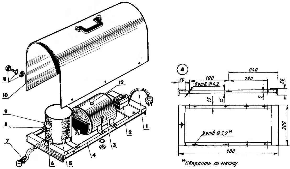
The layout of the compressor:
1 — power cord; 2 — starter batteries of capacitors (from washing machines); 3 — motor-compressor (compression refrigerator); 4 — frame (all elements made of steel strip s1,5): 5 — receiver; 6 — exhaust patroon; 7 — tip-clamp; 8 — bolt, washer, M5 nut; 9 — pressure gauge (9 PC.); 10 cover (steel, sheet s0,8); 11 — a bolt, washer, M4 nut; 12 — the plug of grease
Looking ahead, I will say that subsequently the stator due to overheating of the unit is still out of order and had to be replaced. By the time I left there were already other similar motor-compressor from a discarded old refrigerator. The fact that in the Soviet Union there was only one plant in Odessa, who manufactures motor-compressors for refrigerators of different brands, so most of the parts and components of these units were unified. To replace the stator took a bite out of the clippers the lead ends of the windings and separated the cover from the other (right) hand, gently propilov in a circle the shell to approximately 10 mm from the end. After replacing the stator motor cover did not cover, thus providing additional cooling to the unit.
From the compressor housing removed, the oil pump together with malopriemlema and related fasteners.
In the casing above malopriemlema drilled a hole for the entry of grease, and welded to the sidewall angles, which act as legs, and he did it so that when the unit is installed in working position (on the frame) hole in the casing and socket maloprim-Nika and plunger in the compressor was on top. After that I assembled the unit and fill the volume previously occupied by oil pump, grease LATIN (with grease). Now lubrication as expenditure under its own weight served to the parts of piston group.
The unit has added another device — a small receiver. He serves as maslovlagootdelitel.
The receiver is made from a section of a pipe with a diameter of 100 mm and length 120 mm, tight heat sealing of its ends. In the receiver waril three port: inlet, outlet, pressure gauge. Installed pressure gauge designed for a maximum pressure of 400 kN (4 ATM) — more at home hardly required. Receiver with a compressor connected by the pressure hose. The same hose through a check valve mounted on the exhaust pipe. In the free end of the hose inserted tip-clip from car pump. By the way, in commercially available spray guns, having inlets for compressed air for such tips.
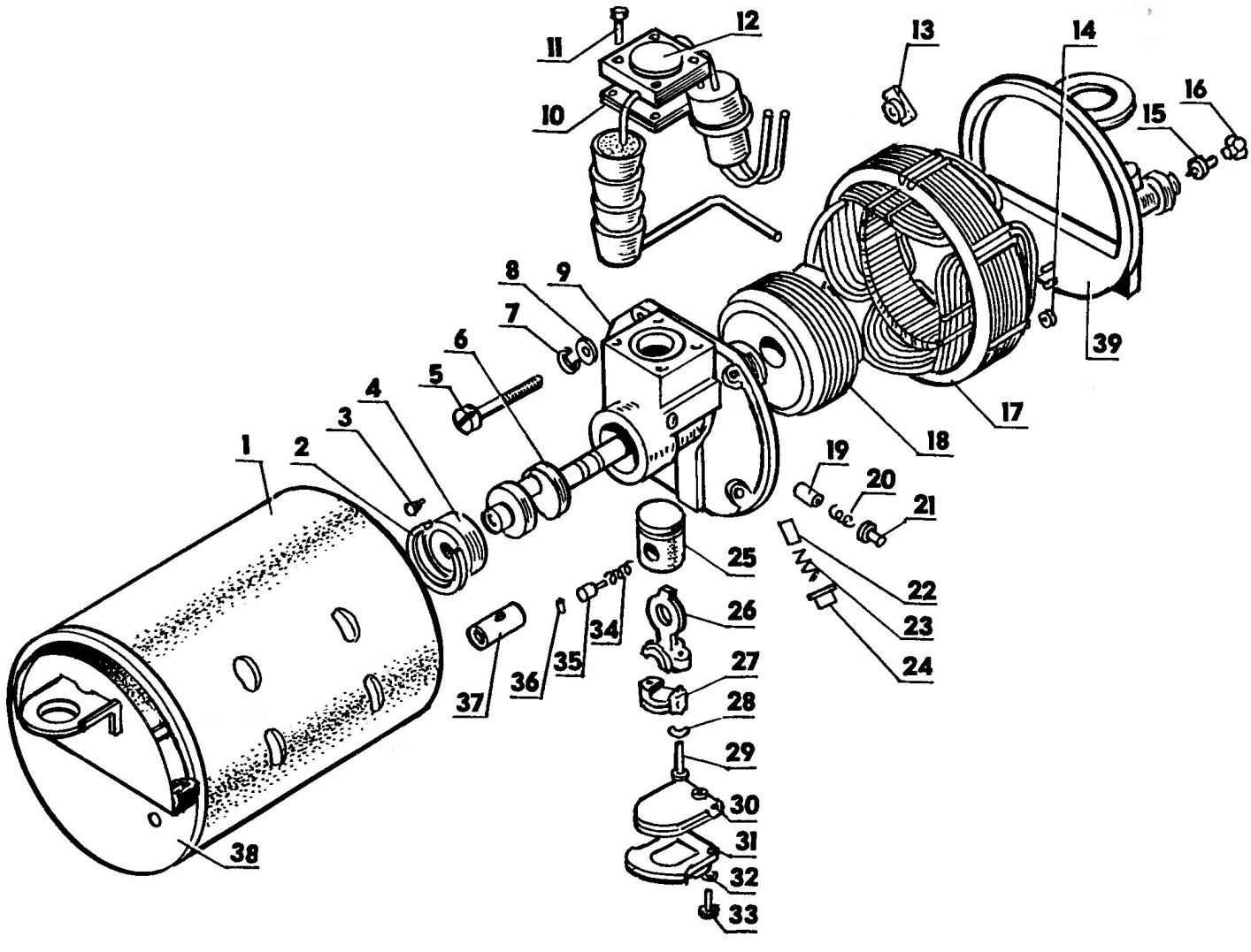
The compressor motor in the casing:
1 —compressor casing; 2—lock ring front bearing; 3 — dowel pin front bearing; 4 — front bearing; 5 — the screw of fastening of the compressor; 6 — crankshaft; 7 — washer; 8 — washer; 9 — the compressor housing; 10 — suction valve; 11 —the screw of fastening of the cylinder head (4 PCs); 12 — cylinder head with silencers in gathering; 13 — flange nut; 14 — shields passing contact; 15 — the shut-off needle; 16 — tube fitting filling; 17 — electric motor stator; 18 — rotor electric motor; 19 — valve; 20 — spring relief valve; 21 — plug of the pressure reducing valve; 22 — the piston of the oil pump; 23 — spring plunger; 24 — end cap oil pump; 25 — a piston; 26 — rod; 27 — cover-connecting rod; 28 — a spring washer; 29 — a bolt of fastening of a cover; 30 — the receiver of the oil pump; 31 — receiver cover oil pump; 32 — spring washer; 33 — a bolt receiver; 34 — spring wedge; 35 — wedge piston pin; 36 — piston pin retainer; 37 — piston pin; 38 — left casing cover; 39— dextral cover of a casing
Drain liquid (oil and water) from the receiver from time to time produce through the exhaust pipe by disconnecting the hose.
To control the unit used the starter from the washing machine “Kama” with two buttons “start” and “stop” and the respective capacitor banks.
All of these nodes mounted on the frame, and the compressor — lying, and the receiver standing up.
The frame is welded from parts of 15×15 mm (longitudinal elements) and 30×30 mm (cross), billets which had previously been hollowed from steel strips with a thickness of 1.5 mm of appropriate width.
And the last one. On top of the unit closed protective cover made of tin with a thickness of 0.8 mm, similar to what was covered before hand sewing machines, but without the end walls. The case is attached to longitudinal elements of the frame are the six M4 screws (three each side). For easy transport the case on top is attached a handle from an old suitcase.
A. PEVNEV, Dimitrovgrad, Ulyanovsk region.
Recommend to read
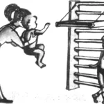 Half a meter of health
Undoubtedly, a home sports complex is necessary for any family, especially a young one. But what if you live in a small one-room apartment or, like my family, in a dormitory room? Under...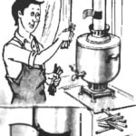 DOOR FOR PIPE
When you put the samovar in the house, the smoke given often through the window pane But when you have to throw in a pitcher samovar wood or coal lumps, the room is filled with smoke. ...

 Pets compression refrigerators usually serve more than a dozen years. But there comes a time when they become obsolete: most not physically, but mentally, as technological progress does not stand still, and it generates more and more perfect such devices. Acquiring a new, old refrigerators are simply thrown away, although some aggregates still could serve, albeit in a different capacity, or for other purposes.