Here I will make an explanation: in the drawings there are other differences from the image of the machine in the photos. The fact that during the operation revealed that some of the units and details it would be better to run a little differently. And these improvements are reflected in the drawings.
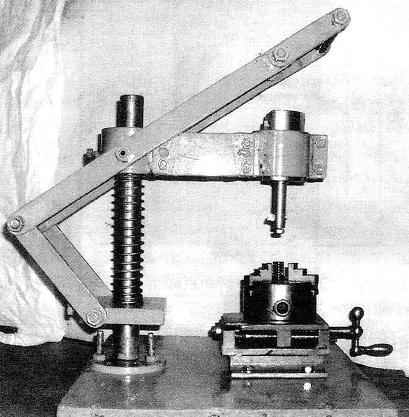
Device (manual machine) for cutting keyways and splines:
1—Foundation (steel plate s20); 2 — front (steel, range d40); 3 — bearing flange (steel); 4 — fastening flange to the base (screw-M12, 3 pieces); 5—holder (steel); 6 — a stopper of the holder (screw M12); 7 — axis lever rod (half stud with M12 nut, 2 pieces); 8—lever rod (steel strip 30×8, 2); 9 — swivel rod lever (bolt M12, 2 PCs.); 10 — the lever (steel strip 30×8, 2); 11—compression spring; 12 — console; 13 — RAM (screw M12); 14—pin (screw M12); 15—fastening of the lever on the axis (Ganka M12, 2); 16 — axis handle (steel, lap 18); 17 — handle (tube d30x18,5); 18 — locking pin-tool holder (steel, circle d64); 19 — cutter; 20 — the stopper (screw M10); 21—trehkanatnoy lathe chucks: 22 — caliper
Near one edge of the base is fixed through a flange strut — steel rod with a diameter of 40 mm and a height of 450 mm. Along the whole stand is cut a longitudinal groove, and one of the youths made a groove for coupling with the flange. Now it became clear to me that it would be a good idea to make the rack higher up to 500 mm — is often a necessity, when it is necessary to make a groove in the long (or high) details (e.g. the hubs), then lift the console is not enough. The flange is a large stepped washer with a Central hole under the counter and three evenly spaced holes with a diameter of 12.5 mm for fixing to the base plate. Are respectively located, but only threaded holes M12 is executed and the table-base. Machined front end inserted into the Central hole of the flange, and the parts are joined by welding, and then the flange is screwed to the base.
On the rack must be mounted slidably to the tool holder and the console compression spring between them.
The tool holder is a rectangular parallelepiped with a small relative size in terms of height with a Central hole under the counter and three M12 threaded holes or two opposing blind-side and one through one of the ends. Of course, the definition of “end” and “side” such geometries are identical, but, I hope, is clear from the drawing. In face hole screwed locking screw of the holder, and the side — studs that serve as the axes of the rods are levers.
The console detail is more difficult. Consists of two hollow cylinder (rack and bridge & overhead), connected by a lintel of steel square pipe sizes 60x60x2,5 by welding. In the body of each of the cylinders is made via the M12 threaded hole in the rack under the retaining screw to keep from turning, and bridge & overhead — under locking screw. In addition, to rack-mount the cylinder in the middle from opposite sides are welded a pair of “polyshelk” M12 (you can use screws with the same thread) — they are the axes for the levers of the tool feed.
Console:
1—rack-mount the cylinder (a circle d80); 2—jumper (pipe 60х60х2,5); 3—bridge & overhead cylinder (tube 80×64); 4—axis arm (stud M12, cut in half, 2 pieces)
Holder on the rack at the desired height locking screw is fixed and serves to support the entire feed mechanism of the tool: the console secured in the holder with the cutting tool and system of levers for longitudinal feed. The rise of the console and hold it in upper position are spring loaded. From turning on the console front holds the locking screw, the end of which, sharpened by a corresponding profile, slides in the longitudinal groove of the rack. Friction surface of the parts before the work is covered by a thin layer (as in firearms) grease.
Bar — detail with which the tool or its holder is fixed in the console. In my case, the mandrel and tool holder is made of 45 steel as one piece in the form of a stepped cylinder with a diametrical hole for the cutter near the free thinner end. Here at the end of the drilled screw hole M10 — through it with the relevant screw the cutter is fixed in the hole of the toolholder. On the cylinder of larger diameter preservada lyska — it rests on the locking screw M12, which does not allow the mandrel to rotate with the occurrence of the torque from the cutter. The same screw keeps the mandrel from falling out of the cylinder of the console. But his efforts on squeezing the bar out of the cylinder when the working stroke may not be enough: for this purpose, the mandrel left shoulder.
The thrust levers and made from steel strip with cross-section 30×8 mm. Levers put on the axis of the cylinder bridge & overhead console, and traction on the axis of the holder. And those and others between bolted-axis hinge.
Between the upper (free) ends of the arms are inserted and secured, the axis of the handle, a cylindrical rod with a diameter of 18 mm with thread M12 at the ends of the groove. Pen itself is made in the form of a sleeve 30×18 mm in diameter, loosely fitting on a greased axle. On the surface of the sleeve the pre-made knurling.
A special story about the caliper of the machine. It looks like a machine vise. A fixed workpiece to be processed in mounted on the upper moving platform of the caliper trehserijnogo the Chuck from the lathe cutting machine. Using calipers is carried out feeding of the workpiece relative to the cutting tool to the cutting depth. Looking ahead, I note that the depth of cut per pass is very small — only 0.2 — 0.3 mm.
The caliper consists of a welded hull and a movable table. Although the welded parts and a few (5 pieces), however they are quite simple — almost all (except the uprights) in the form of rectangular parallelepipeds. Stand is made of angle steel rolling 40×40 area with a half-cut vertical shelf. By the way, the traverse of the hull and cross member of the movable table is the holder (the body) from a broken lathe cutting tools. Anyone have a milling machine, that can easily produce the housing and the ground as one part from solid billet.
Caliper:
1 —front case (40×40 area with cut vertical shelf, 2 PCs.); 2—area of the hull (steel, sheet s7); 3—front cross member (cutter holder); 4—rear cross member (cutter holder); 5—movable table (steel, sheet B7); 6—movable cross-bar of the table (cutter holder); 7—spindle M12; 8—screed left, right, conventionally not shown (винтМ12,2); 9—handwheel with handle; 10—cotter pin d3; 11 —trim (steel sheet s); 12—fastening the lining to the shell (M4 screw, 2 PCs.)
Pre-feeding of workpieces to the cutting tool can be performed “manually” by loosening the screws that secure its housing To the table base, and move the entire caliper in the slots (elongated holes).
The moving platform is carried out from the crank-flywheel screw with normal thread M12. Matrix nuts, as such, no mechanism Corresponding threaded hole, along with a pair of guide holes formed in the crossmember under the ground. Yourself guides — a pair of long screws M12. I must say that the caliper can be moved to a distance of 60 mm, although for cutting grooves and slots, usually more than 10 mm and not required.
As noted earlier, the depth of cut (feed) while working on the machine small. To accelerate the production of “gostovskaya” keyways you can use the one at the beginning of the article drilling technology semi-circular “collective” grooves, and then use the mortising machine to Refine them to the rectangular cross-section.
G. SIRAKOV. Chelyabinsk
Recommend to read UNDER A TREE… IN THE HOUSE There are many different designs of flower stands and brackets for houseplants. However, the green area in the house will be more attractive if the role of stand-pendants flower pots to... WILL NOT SLIP OFF On the door of the wardrobe is usually a wire bracket-hanger for small things: scarves, ties, belts, trying to slip off, fall off when opened. This will not happen if they were to...
 In the conditions of a home workshop without special tools and fixtures can be performed, perhaps, only the so-called “collective” keyway: when impaled on the shaft gear or pulley is drilled by the drill joint hole centered on the circle stitching. Then in this hole is inserted a cylindrical key. But such a connection of the parts securely — no wonder because it is not in any Guest.