DRILL ON THE TABLE

DRILL ON THE TABLEThere was a time when to the store to buy any device, especially metal cutting machine tools was difficult. And was expensive, and a run of outlets had. Today to buy such a product just just pay. But the homebrew is still not translated, offering a new design made based on their capabilities. With the technical creativity of Feodor Nikitovich, Kuhtenko our readers are already familiar (see “M-K” N° 6 – 2012). This time we offer the more complex its design – drilling machine, constructed primarily from what the designer had on hand, though without turning and milling operations has not done.

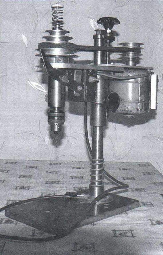
The base of the machine (bed) and a Desk serves as a textolite plate size 300×175 mm and thickness 16 mm. thereto by suitable bolts, turned the heel (by the way, it can be welded) serving as a support and holder of the main stand (columns). The latter is a steel cylindrical rod with a diameter of 28 mm and a length of 430 mm. One end machined to a length of 20 mm and it is threaded M12. This threaded peg subsequently put the bracket screw, which secure it with lock nut (although it is fine and normal). The bracket is made of duralumin sheet thickness of 10 mm. Steel lead screw with trapezoidal thread on the Tg 16×2 length of 200 mm is taken ready – this is some clamps. At its end is mounted the flywheel, and turn the screw. Related sliding nut raises console for a production site (it falls under its own weight when the reverse rotation of the screw), adjusting its position on the rack depending on the height of the workpiece. For “gross” movement of the working node at the front serves as the docking sleeve, which backs suspension (matrix) and the nut is fixed on the rack retaining screw M6 with plastic head button. To insure against breakage of the working tool, on the rack there is mounted a compression spring, cushioning the working node in case of “free” drop.
 
A work node is conventionally called part of the mechanism of the machine consisting of drive and spindle head mounted on their own consoles.
The drive mechanism consists of a console attached to it with three screws to the motor and is mounted on the motor shaft chetyrehvetvevogo unit leading pulleys V-belt transmission. The console can move away from the counter, thereby providing the tension on the timing belt.
 
Looking ahead, we note that the diameters of the pulleys in a block (both in a host and slave) are different and the speed change of the spindle is carried out by rearranging the drive belt from one stream to another.
 
Leading the unit is machined from aluminum and attached to the shaft of the motor with a pin-dowel (item is named so because the pulley is provided with radial threaded hole and the shaft has a keyway), which performs the role of the M6 screw without head. Drive V-belt – the “zero” profile, respectively, of the same type have, and streams unit of the pulleys.
 
Table drill press
 
Table drilling machine:
 
1 – Desk-based (textolite plate s16); 2 – heel (steel, lap 80); 3 – basic strut (steel, lap 28); 4 compression spring; 5 – installation sleeve (steel, lap 45); 6 – locking screw (screw M6, with plastic button head); 7 – screw; 8 – matrix-based Тг16х2 nut; 9 – the console drive (steel, sheet s5); 10 – bracket screw (made of anodized aluminum, sheet s10); 11 – special nut M12; 12 – flywheel screw (plastic); 13 – washer; 14 – the block leading the drive pulleys (made of anodized aluminum, round 69); 15 – motor; 16 – block of capacitors; 17 – the block of the driven pulley (aluminum, circle 98); 18 – restrictive rod return spring (screw M5, with plastic fungus); 19 – a returnable spring of the spindle; 20 – split clamp (made of anodized aluminum, round 76); 21 – spindle head; 22 console spindle head (aluminum sheet s10); 23 – the drive belt (profile 0); 24 – switch; 25 – power cable with plug; 26 – the lever of the instrument (steel, sheet s4); 27 – removable lever handle (tube d12); 28 – tool cartridge No. 2; 29 – M6 screw with washer

 
14
 
20
 
18
 
22
 
9
 
17
 
2
 
9


The spindle head mechanism is more complicated, because it provides both rotational and translational (feed) movement of cutting tools (mainly drills, but can be used and end mill, and grinding head and other metal cutting tools). The spindle head is mounted on a separate (private) console, made of duralumin sheet thickness of 10 mm, and is retained therein by means of retaining clip (split ring), made of the same aluminum sheet as the console.
 
The basis of a spindle head is a steel stationary bushing, machined from “logs” of diameter 50 mm. Better, of course, in order to save metal, to make it of a thick-walled tube of the same outer diameter and a wall thickness of not less than 11 mm, but find this difficult. The outer surface of the sleeve is three – stage. In the wall of the lower, more subtle stage is made rounded longitudinal hole (through-groove) with a width of 6.2 mm and a length of 60 mm (rounded) under the axis of the feed lever of the tool. On the opposite side of the drilled hole under the M6 locking screw; by the way, it is convenient to grease rubbing surfaces. At the top of this sleeve there is a groove under the bearing end of the sleeve.
Block pulleys spindle head similar to the leading block of the pulleys. He also chetyrehluchevoy has pulleys of different diameter and made of aluminum. But its connection to the spindle is a little different. First, a block of pulleys is mounted not on the shaft (spindle) and on the end bushing. Second, this connection provides not only the engagement to transfer the torque as a drive, but, within certain limits, does not restrict the movement of the spindle up and down. In the block of pulleys and a sleeve provided with radial hole M5, and the spindle is a longitudinal groove. Connected, but rather are mutually fixed, the block and the spindle, and the drive also screw M5 without crown, but longer. Besides, its end sharpened so that performing the role of the key, he still has the ability to freely, but without much clearance to slide in the groove.
 
Spindle head
 
Spindle head:
 
1 — spindle (steel, lap 12); 2 – way bushing (steel pipe 28×3); 3 – radial rolling bearing No. 1000900 (2); 4 – M6 screw; 5 – washers-washers (bronze); 6 — lever (steel, sheet s4); 7 — stopper chassis bushing (special screw M6 knurled button); 8 – low nut M12; 9 – stationary bushing (steel, circle 50); 10 – radialogy bearing; 11 – Circlip; 12 – end adapter sleeve (steel, round 20)

 
The spindle is a solid steel rod. At its lower end is made Morse taper tool under cartridge No. 16 for drills with shank diameter from 1 to 9 mm, and near the left end of the stepped flange to clamp the lower bearing. From the other end of the spindle is almost one-third turned to a diameter of 11 mm and a longitudinal slotted groove section 2,5×4 mm (depth x width). At the end of the spindle is made of a threaded socket (blind hole M5) under the restrictive rod return spring.
 
The spindle is mounted on a pair of rolling bearings in the driven bushing and fixed low (small thickness) nut M12 extended from one side sloping chamfer (she is facing the bearing).
Suspension bushing is a tube with internal grooves at the ends under the bearings. Outside, in its upper half, also made several ring grooves-grooves for better lubrication of the friction surfaces of the chassis and the stationary bushings. About the middle of the sleeve threaded radial hole in the axle-screw of the lever. Then the Assembly of spindle and spindle sleeve is placed in a stationary bushing previously inserted into the designated hole in the bracket and attached to this releasable clamp.
 
Driven by Shiv and the return spring, the spring is visible inside the end sleeve and the upper end of the spindle in the upper position
 
Led Shiv and the return spring, inside the spring is visible to the end sleeve and the upper end of the spindle in the upper position
 
Spindle and threaded bushing Assembly
 
The spindle and driving sleeve Assembly
 
Drilling head Assembly
 
Drilling head Assembly
 
On top of the spindle end fits over the adapter sleeve with the fitted angular contact bearing, and on it is mounted the driven pulley unit so that the radial threaded holes of the bushing and the block coincide with each other and with the groove of the spindle. After that, parts are mutually fixed between a screw-key.
 
On the upper end of the spindle fits over the recoil spring compression, it is inserted into the long screw M5 with a hat-fungus and screwed into the threaded socket. The spring should be selected such that it confidently returned to chassis bushing in the original (upper) position, but not so tight that the hand of the master pushing.
 
In the end, on the spindle head on the axis of screw M6 with washers spacers mounted lever with arm feed control of the cutting tool, and a stationary sleeve is screwed the locking screw M6 with the handle button.
 
Electrical circuit did not cite, as the selection of its parts (capacitors) largely depends on the brand of the selected motor. And the motor on the machine is pretty outdated, although quite workable. On his signboard, except for the brand of DPA-U1, there are no inscriptions had worn off. We only know that the engine converted to single phase from three phase. So I will not describe the applied capacitors and their connection to the motor windings.
N. VASILIEV

Recommend to read

  • THE HUNCHBACK OF SEATTLETHE HUNCHBACK OF SEATTLE
    Carrier-based fighter Boeing F4B. Fighter Boeing F4B firms on merit according to the United States one of the best fighter biplanes of the late 20-ies of the last century. He was in...
  • ON SAILINGON SAILING
    Those who live near the water, the boat is as necessary as for other bike or car. Of course, experienced shipbuilders-fans are unlikely to descend to the boat, we want to bring to your...