There was a time when it was difficult to buy any attachment in a shop, and especially a metalworking machine tool. It was expensive, and you had to run around the trading outlets. Today it is easy to get such an item—just pay. But DIY enthusiasts still don’t disappear, offering more and more new designs made according to their own capabilities.
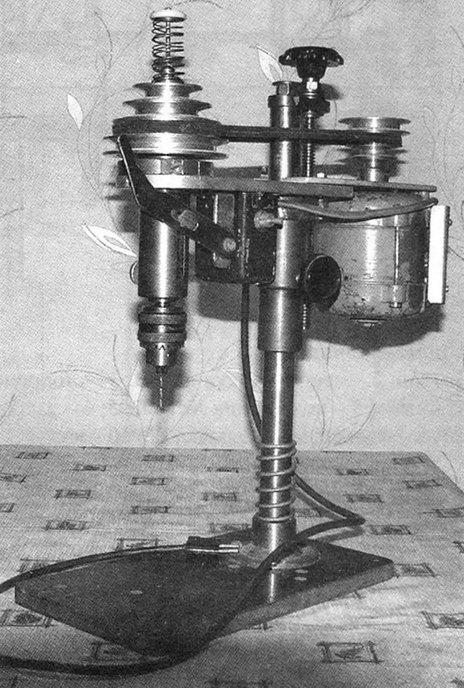
Our readers are already familiar with Fedor Nikitovich Kokhtenko’s technical creativity (see “M-K” No. 6 – 2012). This time we offer a more complex design of his—a drilling machine made mostly from what the designer had on hand, although without turning and milling work it wasn’t possible.
The base of the machine (the bed) and the work table are a textolite plate sized 300×175 mm and 16 mm thick. To it, with suitable bolts, a machined “foot” is attached (by the way, it can also be welded) that serves as a support and holder of the main stand (the column). The latter is a steel cylindrical rod 28 mm in diameter and 430 mm long. One end is turned to a length of 20 mm and threaded with M12. Later, the moving-screw bracket is fitted onto this threaded stud and tightened with a special nut (though an ordinary one will do as well). The bracket is made from a duralumin sheet 10 mm thick. The steel lead screw with a trapezoidal thread Tr 16×2 over a length of 200 mm is taken ready-made — such a one exists on some clamps. A handwheel is mounted on its end, which is used to turn the screw. The lead nut connected to it raises the cantilevers of the working unit (the working unit lowers under its own weight when the screw is turned back), adjusting its position on the stand depending on the height of the part being machined. For “rough” movement of the working unit along the stand, an adjustment bushing is used; it supports the lead (matrix) nut and is fixed to the stand with a locking screw M6 with a plastic push-button head. To protect the working tool from breakage, a compression spring is mounted on the stand, damping the working unit if it “free-falls” unintentionally.
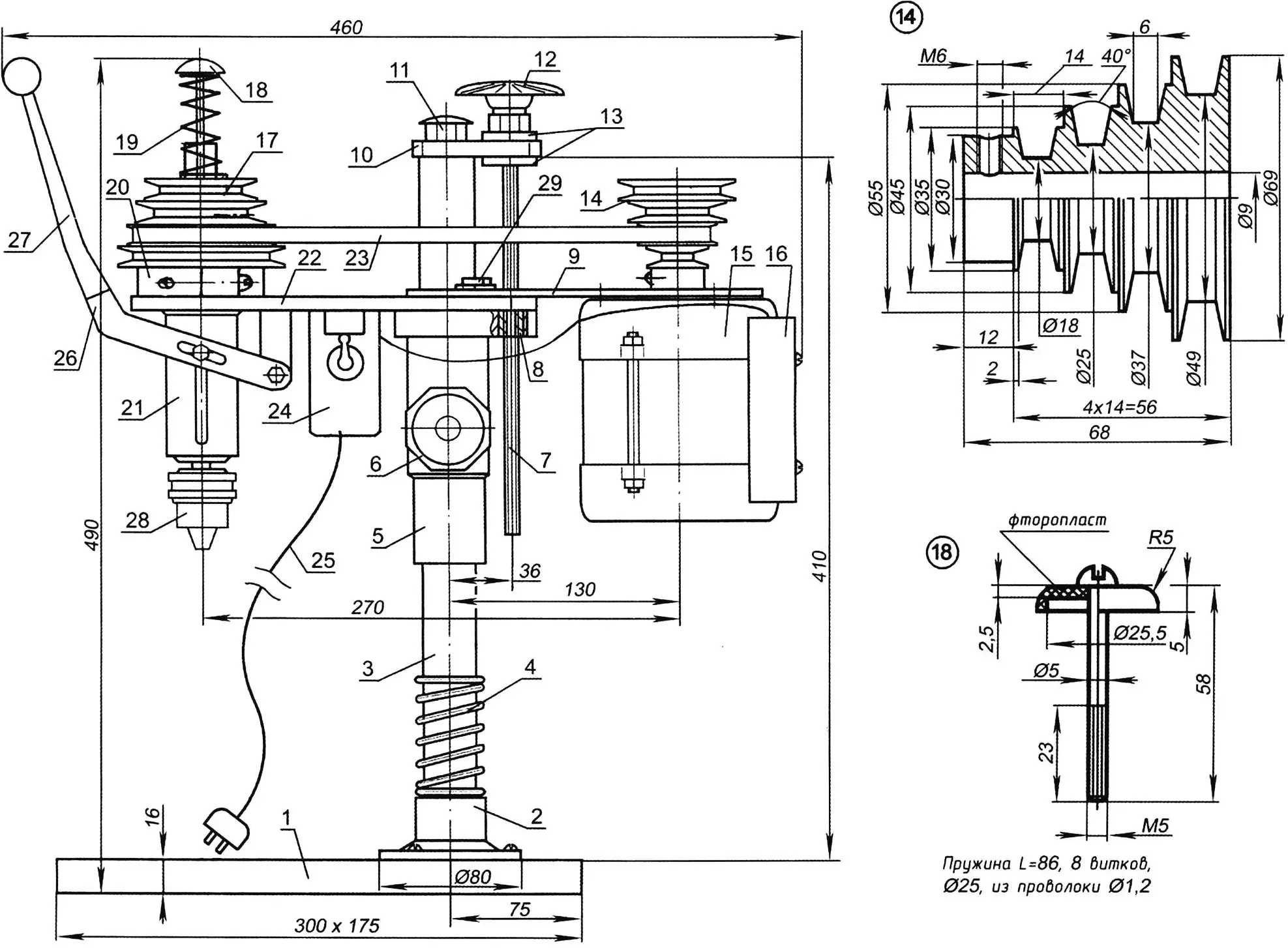
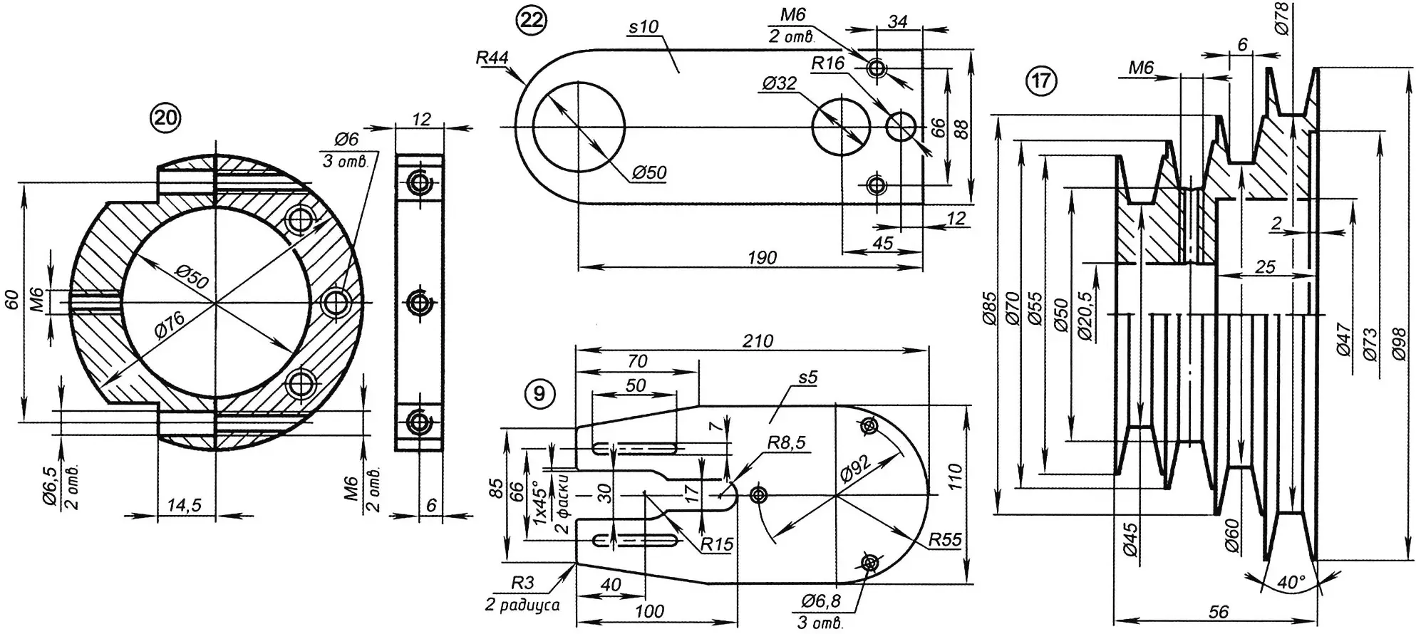
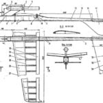
1 – worktable base (textolite plate s16); 2 – foot (steel, diameter 80); 3 – main stand (steel, diameter 28); 4 – compression spring; 5 – mounting bushing (steel, diameter 45); 6 – locking screw (screw M6 with a plastic button-head); 7 – lead screw; 8 – special matrix nut Tr 16×2; 9 – drive cantilever (steel, sheet s5); 10 – lead-screw bracket (duralumin, sheet s10); 11 – special nut M12; 12 – handwheel of the lead screw (plastic); 13 – washers; 14 – block of driving pulley wheels (duralumin, diameter 69); 15 – electric motor; 16 – capacitor block; 17 – block of driven pulley wheels (duralumin, diameter 98); 18 – limiting rod of the return spring (screw M5 with a plastic “mushroom”); 19 – return spring of the spindle; 20 – split clamp (duralumin, diameter 76); 21 – spindle head; 22 – cantilever of the spindle head (duralumin sheet s10); 23 – drive belt (profile 0); 24 – switch; 25 – mains cable with plug; 26 – feed lever of the tool (steel, sheet s4); 27 – removable lever handle (pipe Ø12); 28 – tool chuck No. 2; 29 – screw M6 with washer
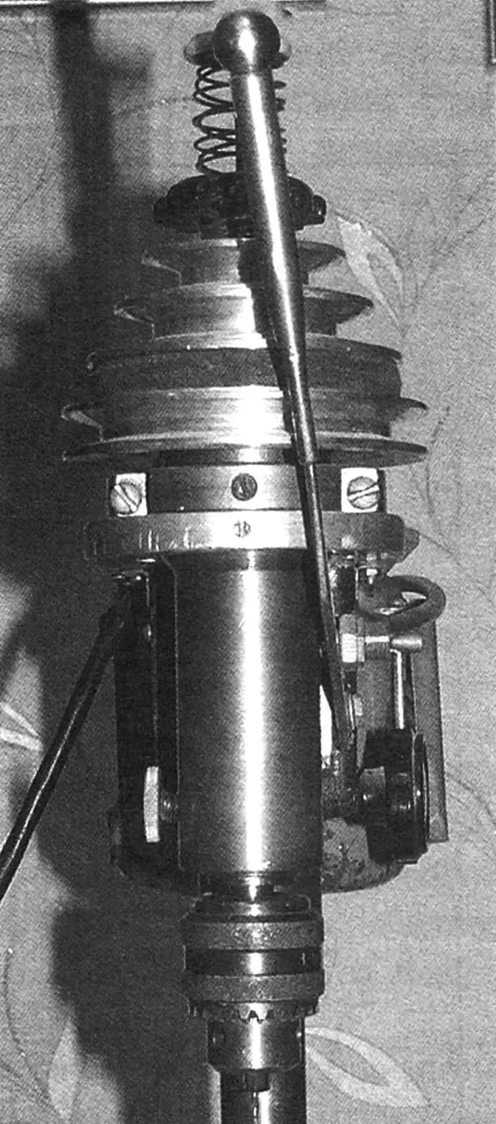
The working unit is conventionally called the part of the mechanism of the machine that consists of the drive and the spindle head, mounted on its own cantilevers.
The drive mechanism consists of a cantilever attached to it with three motor screws and fitted onto the motor shaft of the four-groove block of driving pulleys of the V-belt transmission. The cantilever can move away from the stand, thereby providing tension of the drive belt.
Looking ahead, we note that the pulley diameters in the block (both the driving and driven ones) are different, and the spindle speed is changed by moving the drive belt from one groove to another.
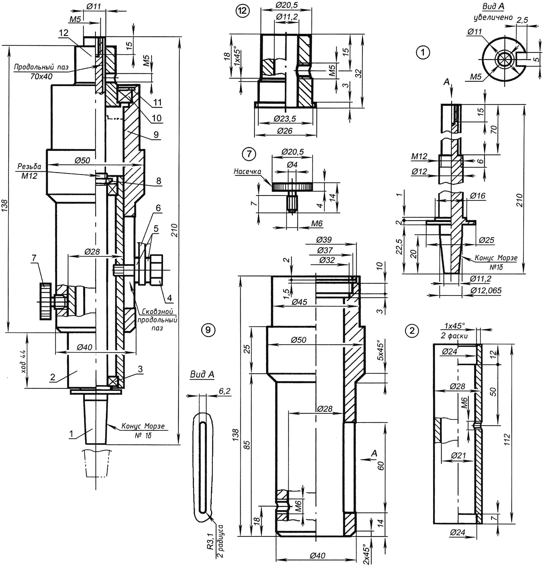
1 – spindle (steel, diameter 12); 2 – lead bushing (steel tube 28×3); 3 – radial ball bearing No. 1000900 (2 pcs.); 4 – screw M6; 5 – shim washers (bronze); 6 – lever (steel, sheet s4); 7 – stop of the lead bushing (special screw M6 with a knurled button); 8 – low nut M12; 9 – stationary bushing (steel, diameter 50); 10 – thrust bearing; 11 – split locking ring; 12 – end transition bushing (steel, diameter 20)
The driving pulley block is machined from duralumin and fixed to the electric motor shaft with a dowel-key (the part is called so because a radial threaded hole is made in the pulley, and a keyway is present on the shaft), whose role is performed by an M6 screw without a head. The drive V-belt is of the “zero” profile; accordingly, the pulley grooves have the same profile.
The spindle head is a more complex mechanism, because it provides simultaneously a rotary and a linear (feed) movement of the cutting tool (mainly a drill; however, an end mill, a grinding head, and other metalworking tools can also be used). The spindle head is mounted on a separate (own) cantilever made from a 10 mm thick duralumin sheet, and is held on it by a clamp (split ring) made from the same duralumin sheet as the cantilever.
The basis of the spindle head is a steel stationary bushing turned from a round bar 50 mm in diameter. Of course, to save metal, it is better to make it from a thick-walled tube of the same outer diameter and a wall thickness of at least 11 mm, but finding such stock is not easy. The outer surface of the bushing is three-stepped. In the wall of the lower, thinner step there is a longitudinal rounded hole (through slot) 6.2 mm wide and 60 mm long (with rounded ends) for the axis of the feed lever. On the opposite side, an M6 hole is drilled for a locking screw; by the way, lubrication of the sliding surfaces can be conveniently done through it. In the upper part of this bushing, inside, there is a groove for the bearing of the end bushing.
The pulley block of the spindle head is similar to the pulley block of the drive. It is also four-groove, has pulleys of different diameters, and is made of duralumin. But its connection to the spindle is somewhat different. First, the pulley block is fitted not onto the shaft (spindle), but onto the end transition bushing. Second, such a connection provides not only engagement for transmitting torque, as on the drive, but also, within certain limits, does not prevent the spindle from moving up and down. For this purpose a radial hole M5 is made in the pulley block and in the bushing, and a longitudinal keyway is made in the spindle. The pulley block and the spindle are connected (more precisely, mutually fixed) with an M5 screw without a head, just like on the drive, but longer. In addition, its end is sharpened so that, acting as a key, it can also slide freely in the keyway, but without a large clearance.
The spindle is a steel solid rod. At its lower end there is a Morse taper for tool chuck No. 1b for drills with a shank diameter from 1 to 9 mm, and near the end a stepped collar is left to fix the lower bearing. From the other end, the spindle is turned down for almost one third to a diameter of 11 mm, and on this section a longitudinal slot is cut with a cross section of 2.5×4 mm (depth x width). At the spindle end face, a threaded seat (a blind hole M5) is made for the limiting rod of the return spring.
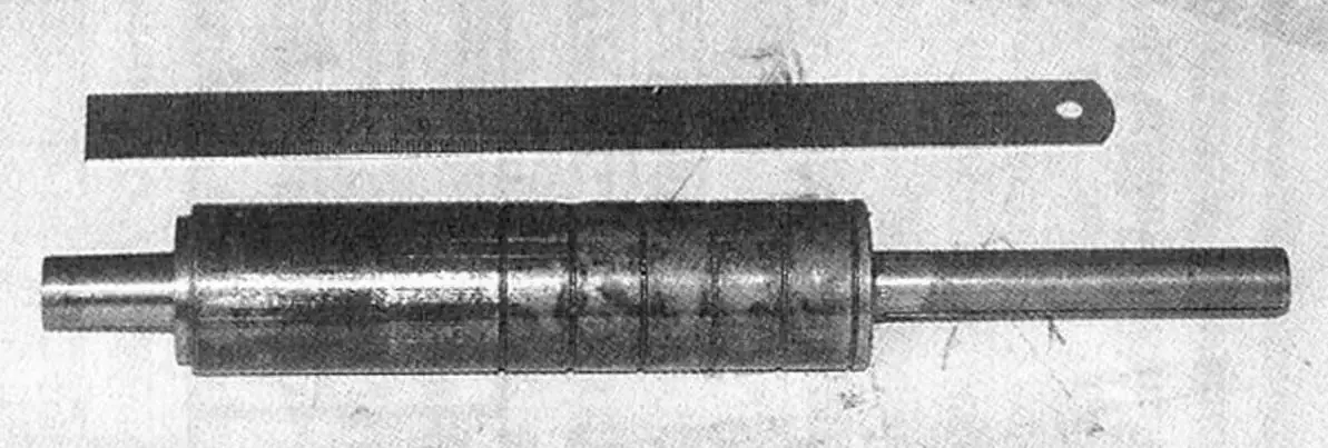
The spindle is mounted on a pair of ball bearings in the lead bushing and fixed with a low (thin) nut M12 with an enlarged slope on one side (the slope faces the bearing).
The lead bushing is a tube with internal grooves at its ends for ball bearings. Externally, in its upper half, several annular grooves are also made—for better lubrication of the sliding surfaces of the lead and stationary bushings. Approximately in the middle of the bushing there is a threaded radial hole for the axis-screw of the lever. Then the assembly of the spindle and lead bushing is placed into the stationary bushing, previously inserted into the hole intended for it in the cantilever and secured here with a split clamp.
On top, the end transition bushing is put onto the spindle with a radial-thrust bearing, and the driven pulley block is mounted onto it so that the radial threaded holes of the bushing and the block coincide with each other and with the spindle keyway. After that, the parts are mutually fixed by a screw-key.
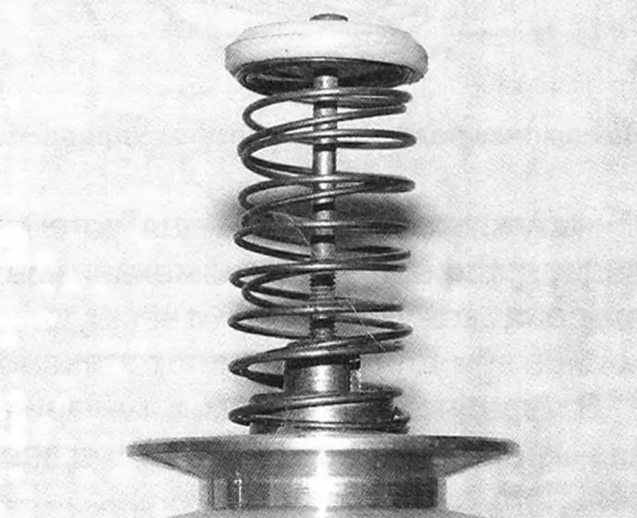
On the upper end of the spindle a compression return spring is mounted; a long screw M5 with a mushroom-head is inserted into it and screwed into the threaded seat. The spring should be selected so that it reliably returns the lead bushing to its initial (upper) position, but not so stiff that the operator’s hand is heavily strained.
In conclusion, a lever with a feed control handle of the cutting tool is mounted on the spindle head along its axis on the M6 screw with shim washers, and an M6 locking screw with a push-button handle is screwed into the stationary bushing.
I do not provide the electrical circuit, because the selection of its parts (capacitors) largely depends on the brand of the chosen electric motor. And the electric motor on the machine is already rather outdated, although it is fully functional. On its nameplate, apart from marking DPA-U1, there are no other inscriptions left — with the years they have worn off. It is only known that the motor was converted from a three-phase to single-phase. Therefore, I will not describe the capacitors used and the wiring scheme of connecting them to the motor windings.
“Modelist-Konstruktor” No. 12’2012, N. VASILIEV
Recommend to read
 RC ROCKET PLANE
In 1980, the sub-Commission on the rocket modeling of the FAI decided to introduce a new class of raketoplana S8E with a maximum mass up to 300 g engine with a total impulse of 40 n*S.... RELIABLE ASSISTANT FOR A POWER TILLER
We continue the story about machines and mechanisms built by V.A. SVERBIL — an amateur designer from the village of Zelenchukskaya in the Karachay-Cherkess Republic. In the publication...
