 The drill — tool is handy and versatile, no wonder it enjoys great popularity among home craftsmen. The drill can do everything: drilling, sanding, polishing, sharpening and even to cut firewood. But the main thing — of course, drilling. Hang a mirror, ledge, bookshelf, strengthen, loose furniture, hang or repair the door (you can enumerate a very long time) — almost no work is complete without drilling.
But, unfortunately, not always fixed hand drill provides the necessary quality of processing, for example, when drilling relatively deep and (or) accurate holes. Even experienced artists do not often manage to maintain the direction of drilling and not to break the hole. And when you run a large volume of work manually physical exertion does not bring great joy. In such cases, usually the thought occurs: “And it would be good to have in your Arsenal boring stanochek, albeit small, at least the table…” it would Seem, no problems, went to the store… But first, it’s expensive, not everyone can afford, and secondly, for any self-respecting wizard be ashamed to buy something that you can do yourself.
When I had this problem, I decided (probably like many before me) to design and fabricate a stand to use the drill as a bench drill.
When thinking of designs, I proceeded from the following assumptions:
1. The rack must ensure the straightness of displacement and perpendicularity of the tool relative to the table.
2. Design should be simple, adaptable, with minimal use of machine tools for manufacture of parts.
In further revisions, accumulated over many years of reserves of all kinds of parts, materials, old appliances, and technical devices (which seems to have and not need, and throw a pity), I came across an old photographic enlarger of the type “Youth”. Understand that this is just what I need: already by its appearance it resembled the drill press. Only had the projector replaced by a power drill and mount the feeder. As a result of “trial and error” was a proposed device is presented in figure 1.
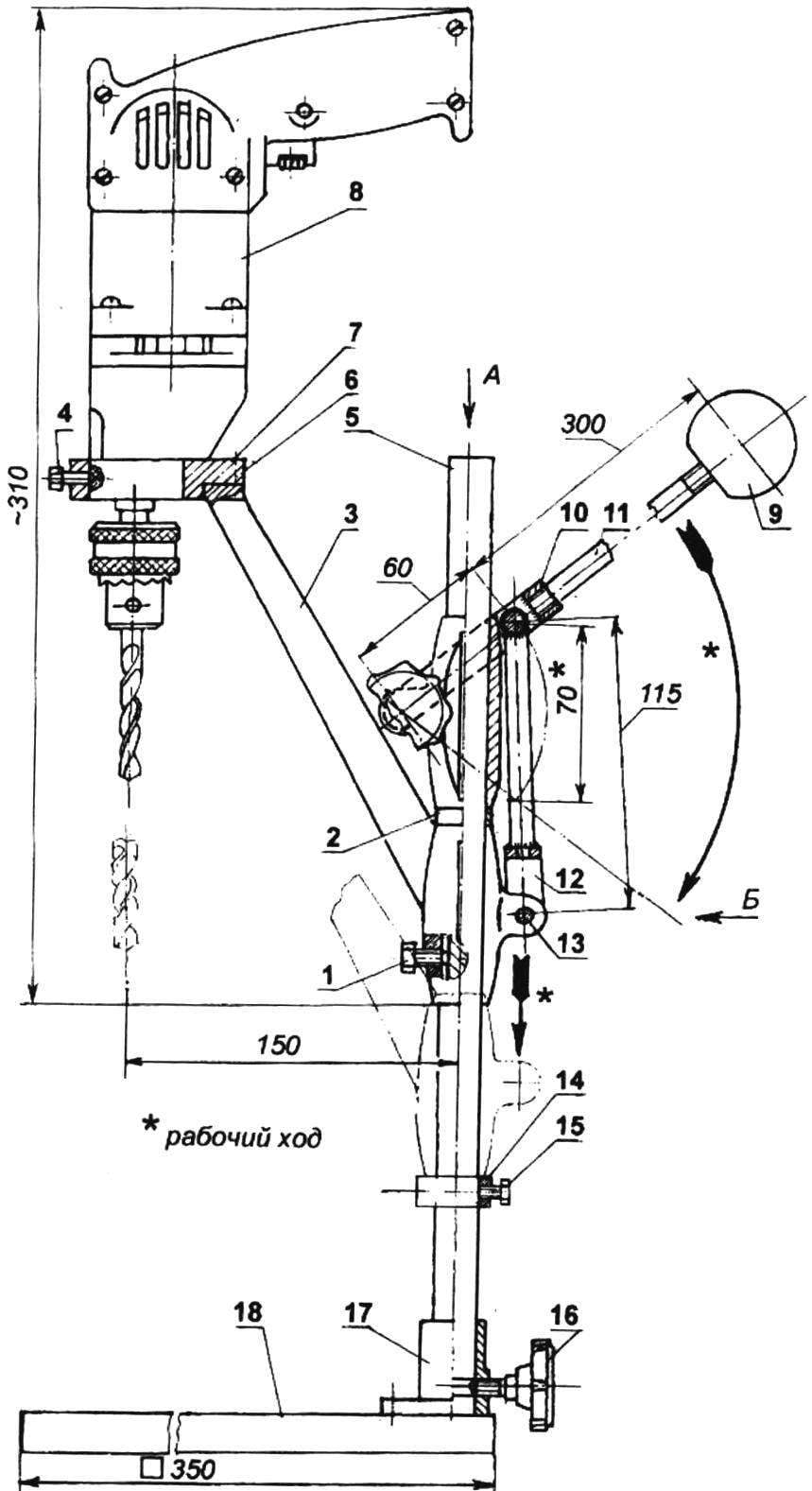
Description of the DESIGN (Fig.1). The drill (8) three lock screws M6 (4) is rigidly fixed to the yoke (6) fixed on the cantilever part of the bracket of the slider (3). Stroke is leverage. By rotating the handle (det.9, 10, 11) around the axis (det. 19, 22), fixed on the supporting sleeve (21), a pusher (12) moves the bracket-slide on the stand (5) downwards. The greatest stroke of 70 mm. To facilitate the return of the drill to its original position between the clamps and the support sleeve (19) and bracket (24) install the tension spring (on the drawing conventionally not shown). The straightness of the movement of the tool is provided with a guiding screw (1) mounted in barrel bushing bracket, and the guide keyway, progressirovanii in the rack along a generatrix. Remote washer (2) is used to ensure optimal position of the lever.
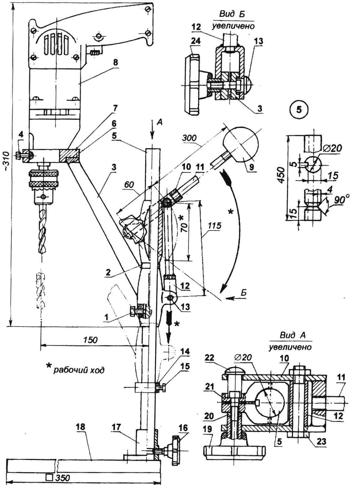
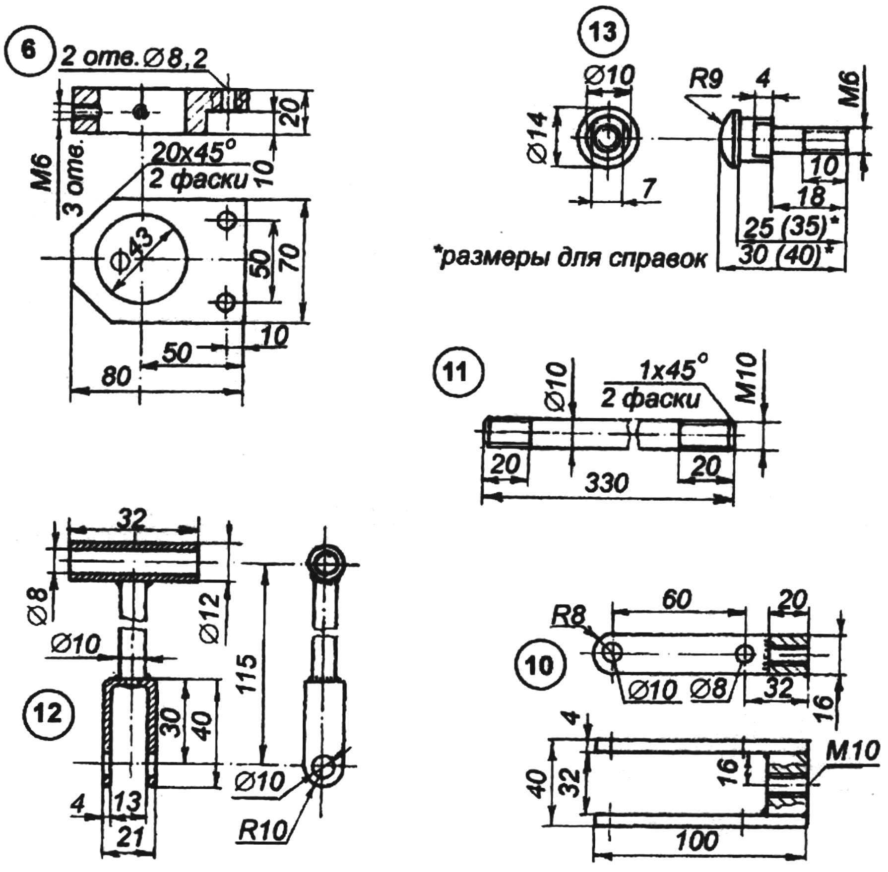
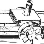
Fig. 1. Bench drilling machine on the basis of the drill:
1 — guide screw M6; 2 — remote washer (tube 24×2); 3 — bracket; 4 — locking screw drill (M6, 3 piece); 5 — stand; 6 — yoke (steel sheet s20); 7 — fastening cage (bolt M8 2); 8 — drill mod. 1036 e); 9 — lever handle; 10 — bracket arm (weldment); 11 — rod lever (M10 L330); 12 — the pusher (welded product); 13 — axis-clamp bracket (ring has ø 14-ø); 14 — restrictive bushing (tube 24×2); 15 — locking screw M6 limiter; 16 — a stopper rack; 17 — slot rack; 18 — desktop; 19 — clamp bearing sleeves; 20 — a remote washer; 21 — a support sleeve (modified bracket photographic enlarger); 22 — axle-retainer bearing sleeves (ring has ø 14-ø); 23 — hinge pin (bolt M8); 24 — clamp bracket; det.3,5,16,17,18,19,24 from enlargement program “Youth”
Swivel lever with support bushing and rod bushing bracket of the same type, and each consists of two elements: axis-lock and clip (types A and B in Fig.1). The design and dimensions of these parts allow for a rigid mounting of the bushings on the rack and at the same time not pinch the cheeks of the forks and pull the lever, ensuring their free rotation.
SETUP drilling installation for processing specific details as follows. The part is placed on the table. The clamps (19) and (24) are attenuated, and the whole system lowered to touch the drill with the surface of the part. Moving it on the table, the drill is placed at the center of the processed hole. To facilitate this operation provides an additional degree of freedom of the working body — rotation stands in the nest together with the mounting bracket and drill with the fixation of a stopper (16). Exposed item is fixed on the table (its attachment in this material are not considered). Then the restrictive bushing (14) is lowered and fixed, providing the distance between its upper end and the lower end of the barrel sleeve of the bracket, equal to the depth of drilling. In conclusion, the bearing bushing (21) is lifted by 3 to 4 mm and is fixed by clip (19).
THE MANUFACTURE AND ASSEMBLY OF
Table (18), Jack (17), retainer (16), clamps (19 and 24) borrowed from the photographic enlarger without change. Bracket (3) has undergone minimal modifications: in the lower part of the hub feature threaded M6 hole under the guide screw (1). In column (5) machined groove of triangular shape under the stopper at a distance of 15 mm from bottom end and along the axis profiterole guide slot 5×5 mm. the accuracy of this operation should pay special attention, as it affects the straightness of the movement of the tool during drilling. The bearing bushing (21) is obtained by adapting another instance of the bracket (Fig.2A): cut off the console and ground off the lateral surface to a size of 30 mm.
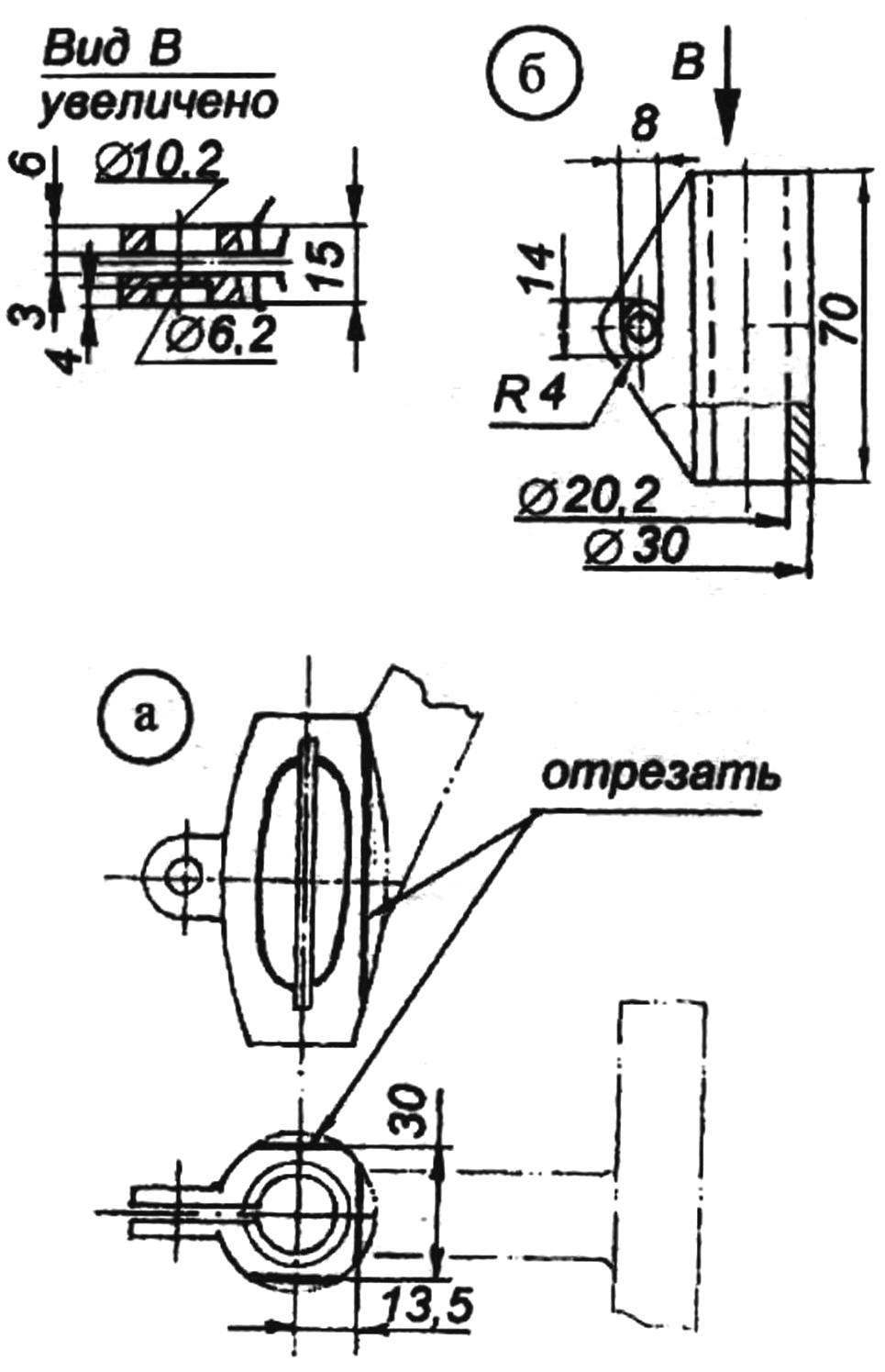
Fig. 2. Support sleeve:
a — finalization of the bracket of photographic enlarger; b — weld option
If the additional bracket is not, then the bushing is not difficult to make yourself (Fig.2B).
Making elements of the mechanism of flow problems is not. Clamp lever (10) is welded from two side plates (strip 16×4 mm) and paste (cut sheet at 20 mm). The stem (11) — stud M10 length 330 mm Tappet (12) consists of three simple parts connected by welding sleeves (pipe with an inner diameter of 8 mm), rod (a rod with a diameter of 10 mm) and brackets, bent from strips with a thickness of 4 mm (the holes for the axle in the bracket should be drilled after bending to ensure their alignment).
Axis-clamps (13 and 22) machined on a lathe from a rod with a diameter of 14 mm. the Processing of basic surfaces of a cage (6) is a hole with a diameter of 43 mm and ledge — should be done on a milling machine with a single installation. This technology will provide in the Assembly of parallelism between the axes of drill and stand, and therefore perpendicular to the table.
Describe in detail the Assembly is not necessary, everything is clear from the drawings. One note: before installing the bracket on the rack on the inner sliding surface of the sleeve apply grease.
V. USTIN, Moscow
Recommend to read
 WITH PROPELLER… WHEELS
It's amazing — currently none of our rivers has not remained exotic steamers with paddle wheels, and any boy youngsters will surely be able to tell how these look! There is something...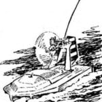 The AIRBOAT
RC model aerolaser (Fig. 1) easy to manufacture, and it does not require scarce materials. Do this even for a Modeler with a little experience, and so the airboat could become a learning...
