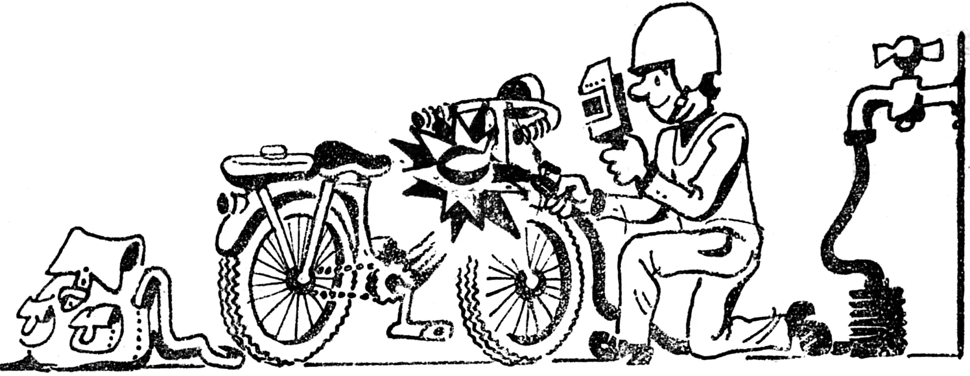
Anyone who reads the description of the electrolyzer I developed will be convinced that a few liters of water are enough to obtain a high-temperature flame (200° C).
The high flame temperature makes it possible to solder ferrous and non-ferrous metals with practically any refractory solders, or with the metal itself (welding). The high concentration of heat in a narrow spot makes it possible, for example, to burn holes Ø2 mm and larger in thin sheet steel, to carry out heat treatment of tools, and to perform shaped cutting of thin sheet steel.
The “water” torch can also be used to process enamels, ceramics, and glass, including quartz glass. For this purpose, however, the flame temperature is increased by 5000° C (the method is not described here). The resulting flame is noiseless, and the absence of carbon in its composition ensures smokelessness. The combustion by-product is simply superheated water vapor, which has no color or odor.
Designed for construction by any skilled amateur, the device has an extremely simple design with no cylinders, regulators, valves, or a complex torch.
The block diagram looks like this:

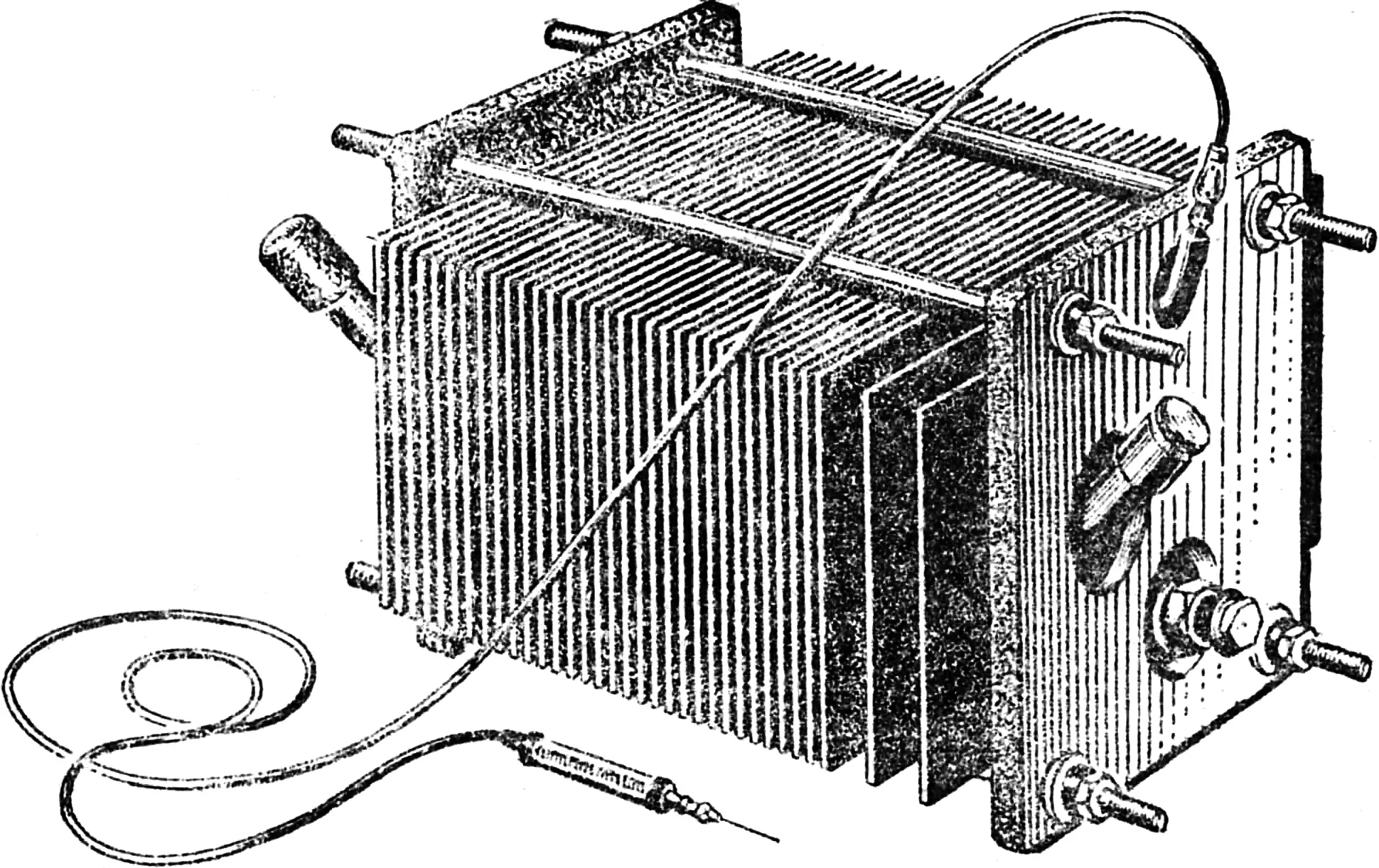
The main part of the device is the electrolyzer; it consists of a series of sealed cavities formed by electrodes, gaskets between them, and plates. The assembled pack is sealed by tightening with bolts.
The cavities are filled with electrolyte through a filling tube; its level is limited by the upper end of the tube. A hole in the lower part of each electrode serves for uniform filling of each cavity with electrolyte. The lower pipe is intended for draining the cavities. Both tubes are sealed shut.
During electrolysis, the oxygen-hydrogen gas mixture formed passes through a hole in the upper part of each electrode into a settling tank divided into two parts by a partition. From there, the mixture enters the water trap through a fitting and hose, bubbles through a layer of water, and then passes through a hose into the torch.
No less important is the water trap. It separates the supply and discharge gas hoses by a column of water 120—150 mm high, through which the gas bubbles. The trap reliably protects the electrolyzer from an accidental flash of gas in the torch hose.
Its body is made from a metal pipe Ø 100 mm, welded shut at both ends. Water is poured in through a pipe until it reaches the upper control level. The tap is at the lower longitudinal level. A grid supports a filter made from any granular non-combustible material. The filter prevents moisture from being carried away by the gas. The gas inlet tube ends in a conventional check valve. The body also contains a check valve with a flare that operates in the event of an accidental gas flash.
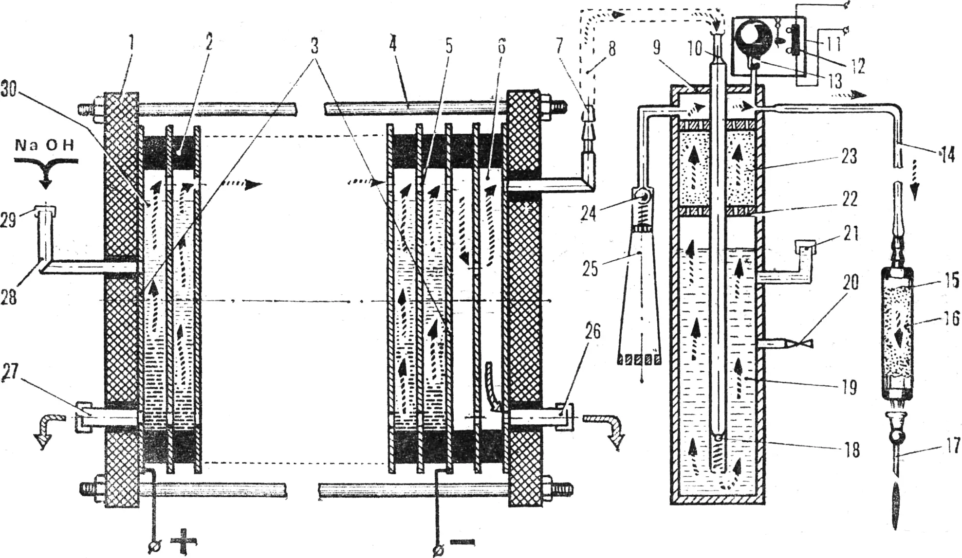
1 — plate, 2 — gasket, 3 — electrodes, 4 — clamp bolt, 5 — hole for gas mixture, 6 — settling tank with partition, 7 — fitting, 8 — hose, 9 — water trap body, 10 — gas inlet tube of the trap, 11 — circuit breaker body, 12 — contactor, 13 — rubber bulb, 14 — hose to the torch, 15 — torch handle, 16 — flame arrester packing, 17 — hollow needle, 18 — check valve, 19 — water column, 20 — lower water level tap, 21 — filling pipe, 22 — filter grid, 23 — filter, 24 — emergency check valve, 25 — flare, 26 — settling tank drain pipe, 27 — electrolyte drain pipe, 28 — filling tube, 29 — screw plug, 30 — electrolyte.
The automatic voltage circuit breaker is homemade. It consists of a body, a contactor, and a rubber bulb. The cavity of the latter is connected to the cavity of the water trap. When the pressure in the system is exceeded, the bulb inflates and, by pressing on the contactor lever, disconnects the device from the mains.
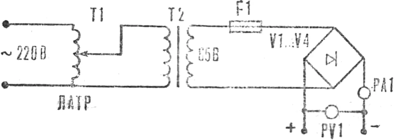
The rectifier electrical diagram consists of the following elements: laboratory autotransformer — LATR 2 kW, step-down transformer 220/65 V, diode bridge rated for 15 A (of any design), fuse rated for 20 A, ammeter (scale not less than 15 A), voltmeter.
The rectifier is connected to the electrolyzer in a bipolar manner, as shown in the diagram.
CALCULATION AND MANUFACTURE
According to Faraday’s law, during electrolysis the amount of substance released is proportional to the current. Theoretically, every 28.7 A yields 11.7 l of hydrogen and 5.85 l of oxygen. In practice, current efficiency is never 100%. The voltage drop across each pair of electrodes (calculated) is 2 V. The current density per 1 dm2 of electrode area depends on the duration of continuous operation of the electrolyzer and ranges from 2 to 5 A.
The simplicity of the design made it possible to reduce the number of main parts to three: electrode, gasket, and plate.
Electrode — decapped sheet or transformer iron 250 X 250 mm thick 0.3—0.5 mm (32 pcs.). Gasket — medium-hardness rubber (flange type), ring Ø 220 X Ø 250 mm, thickness — 4—6 mm (31 pcs). Plate — any insulating material (sheet) 300 X 350 mm, thickness not less than 20 mm (2 pcs.). Clamp bolts — M12 made of steel 45, length — as required (not less than 4 pcs.).
The electrolyte is a 22% solution of caustic soda (NaOH) in distilled water. As it is consumed (total amount 4 l), only distilled water is added to the electrolyzer.
Before filling with electrolyte, the assembled electrolyzer must be tested for tightness by filling it under pressure with water from the mains; the slightest leaks must be carefully eliminated. During operation of the electrolyzer, the electrolyte must not be allowed to heat above 65°.
Because the composition of the gas mixture produced by the electrolyzer is constant, the requirements for the torch are also simplified. It can be an ordinary injection needle from a medical syringe, or rather a set of needles of different diameters, from 0.3 to 1 mm. The needle is mounted on the fitting cone of the handle in the same way as on a syringe. The torch handle is a section of tubing to which gas from the water trap is supplied through a fitting and hose. Inside the handle is flame-arresting packing in the form of fine metal shot and mesh.
Chlorvinyl tubing Ø 4—5 mm is used as hoses.
SAFETY RECOMMENDATIONS
It should be remembered that the hydrogen-oxygen mixture produced by the electrolyzer is explosive!
However, the device itself presents no danger if it is made carefully and used properly. This is achieved because there are no intermediate vessels of significant volume; the gas does not accumulate anywhere: as much as is produced is consumed by the flame at the same time.
However, it is strictly forbidden to fill any vessels with the resulting gas mixture for technological purposes, and especially children’s inflatable balloons. Under no circumstances should the tightness of connections in the electrolyzer structure be checked with the flame of a candle, match, or other open fire; it is also unacceptable to operate without filling water to the upper control level in the water trap or without systematically checking that the water poured in before starting work is still present. A drop in electrolyte level is also dangerous. Distilled water must be added constantly as the electrolyte is consumed.

When preparing the electrolyte, protective goggles and rubber gloves should be worn.
The working flame should be extinguished not by switching off the power, but by lowering the needle into a container of water; otherwise the needle will overheat and fail.
The operator must work with the torch wearing light-protective goggles.
In conclusion, a few words about prospects. Designers know that there are no machines, apparatuses, or devices that cannot be improved. This also applies to the electrolyzer. For example, the rectifier can do without a LATR and transformer without reducing operational quality; the electrolyzer itself can do without rubber or other gaskets; the operating mode can be made continuous; the flame temperature can be raised from 2000 to 3000°.
Across the vast territory of the USSR there are many places seasonally cut off by impassable roads or too far from supply bases. For those working in such conditions, the author developed a model of an electrolyzer that delivers gas under pressure, specially for one-off, for example emergency, jobs requiring high flame power.
I hope to carry out, together with interested readers, a broad test of this development, which seems to me promising.
TECHNICAL SPECIFICATIONS OF THE ELECTROLYZER
Supply voltage, V — 220
Power consumption (adjustable), W — up to 1000
Water consumption at maximum power, g/h — 60
Operating (adjustable) gas pressure, atm — up to 0.3
Gas output at maximum power, l/h — up to 150
Maximum flame thermal energy, kcal/h — 500
Coefficient of conversion of electrical energy into chemical energy — 0.7
Mixture composition (oxygen and hydrogen in exact ratio) — 1:2
Flame size (needle-like) maximum diameter — up to 5 mm maximum length (adjustable) — up to 150 mm
Stable needle-like flame temperature — 2000°
«M-K» 7’80, S. SEROV, Tallinn
Recommend to read
 BYLINA: COLOR AND MUSIC
(The end. The beginning see in number 1). Last time we talked about electromyographical and the stereo amplifier is a musical complex. Today we will talk about it "Svetogorska"... PUMP… CYLINDER
Ingenuity rural operators will not refuse. I had the opportunity again to be sure, when one major economy saw operating safely pumps made by local craftsmen from the brake cylinders...
