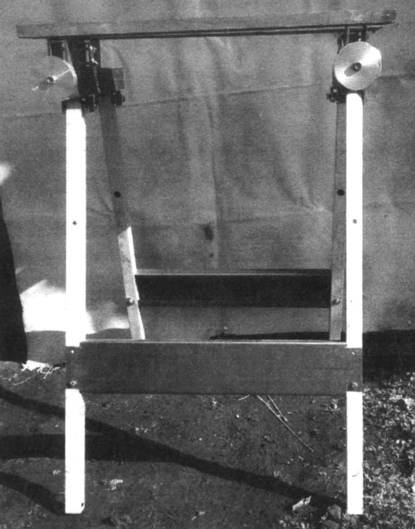
I arrived at the design of this universal (as I believe) workbench — an essential work table for a home craftsman — after several years of technical creativity. I designed it based on my own needs. But I think that most other home handymen have roughly the same requirements for similar workshop equipment. The workbench is foldable and compact in size. However, thanks to an original clamping unit, it can hold fairly large parts and workpieces for machining, mounting them both in a vertical plane and at several fixed angles.
The layout of the workbench is such that it can be divided into three parts: the base, the clamping units, and two work tables. But these parts are conventional — the bench is broken down into them for transport, while for compact storage it can be disassembled into smaller units and even individual parts.
The base consists of four legs made from square tubing 40x40x2 mm in cross-section. The upper ends of the legs are rounded, and the holes are closed with welded plugs so that the tube walls are not crushed when the legs are bolted to the clamp unit body. I left the lower ends of the legs unplugged so that the workbench would not slide on a hard floor. If the bench is to be set up on soil, steel plates should be welded to the lower ends as foot pads.
At the top, the legs are joined in pairs to the clamping units, and along their height they are fixed with crossbars, composite stretchers, and braces made from 2-mm steel strips bent into 20×20 mm angle sections.
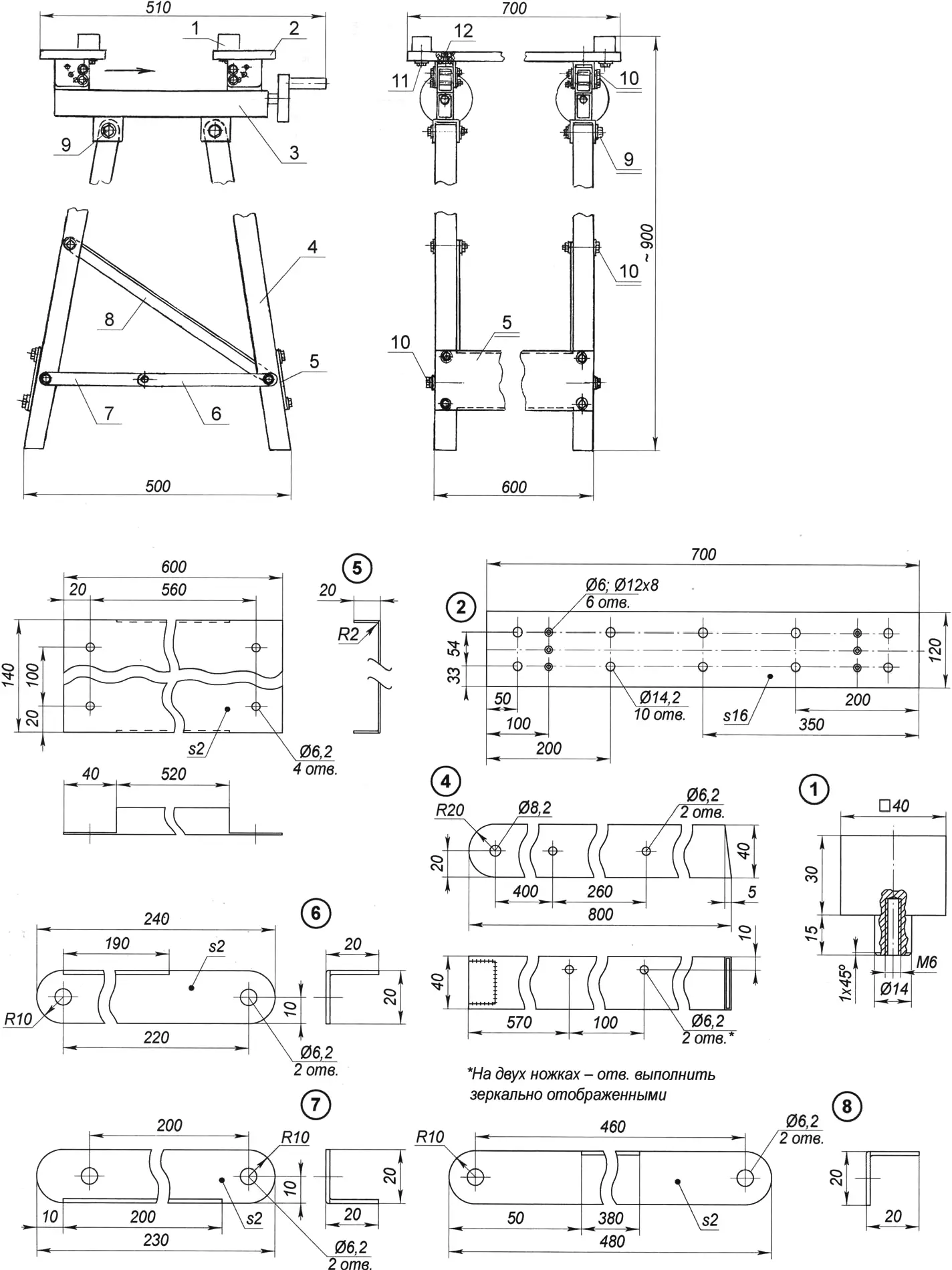
1 — boss (D16T duralumin, 40×40 square, 4 pcs.); 2 — table (chipboard, s16, 2 pcs.); 3 — clamping unit (2 pcs.); 4 — leg (40×40 tube, 4 pcs.), two parts — mirror images; 5 — crossbar (steel, channel from s1.5 sheet; 2 pcs.); 6 — long stretcher (steel, 20×20 angle from s1.5 sheet); 7 — short stretcher (steel, 20×20 angle from s1.5 sheet); 8 — brace (steel, 20×20 angle from s1.5 sheet); 9 — fastening of the clamp unit to the legs (M8 bolt with nut and two washers, 4 sets); 10 — fastening of bracing parts (M6 bolt with nut and two washers, 16 sets); 11 — fastening of bosses to the table (M6 screw with washer, 4 sets); 12 — fastening of the table to the bracket (M6 bolt with countersunk head, 6 pcs.)
The leg height can also be chosen differently, adjusted to suit your height. The clamping unit (there are two of them) consists of a body (a section of rectangular tubing 50x30x2 mm), a lead screw (M12 construction stud) with a nut and a handwheel with a handle.
The lead screw is placed in the body with the nut screwed onto it and mounted in it on two supports. The supports are made of softer steel and therefore serve as plain bearings for the screw ends, lubricated with grease.
One support (on the handwheel side) is welded to the body, and the other is fixed with two M3 countersunk-head screws.
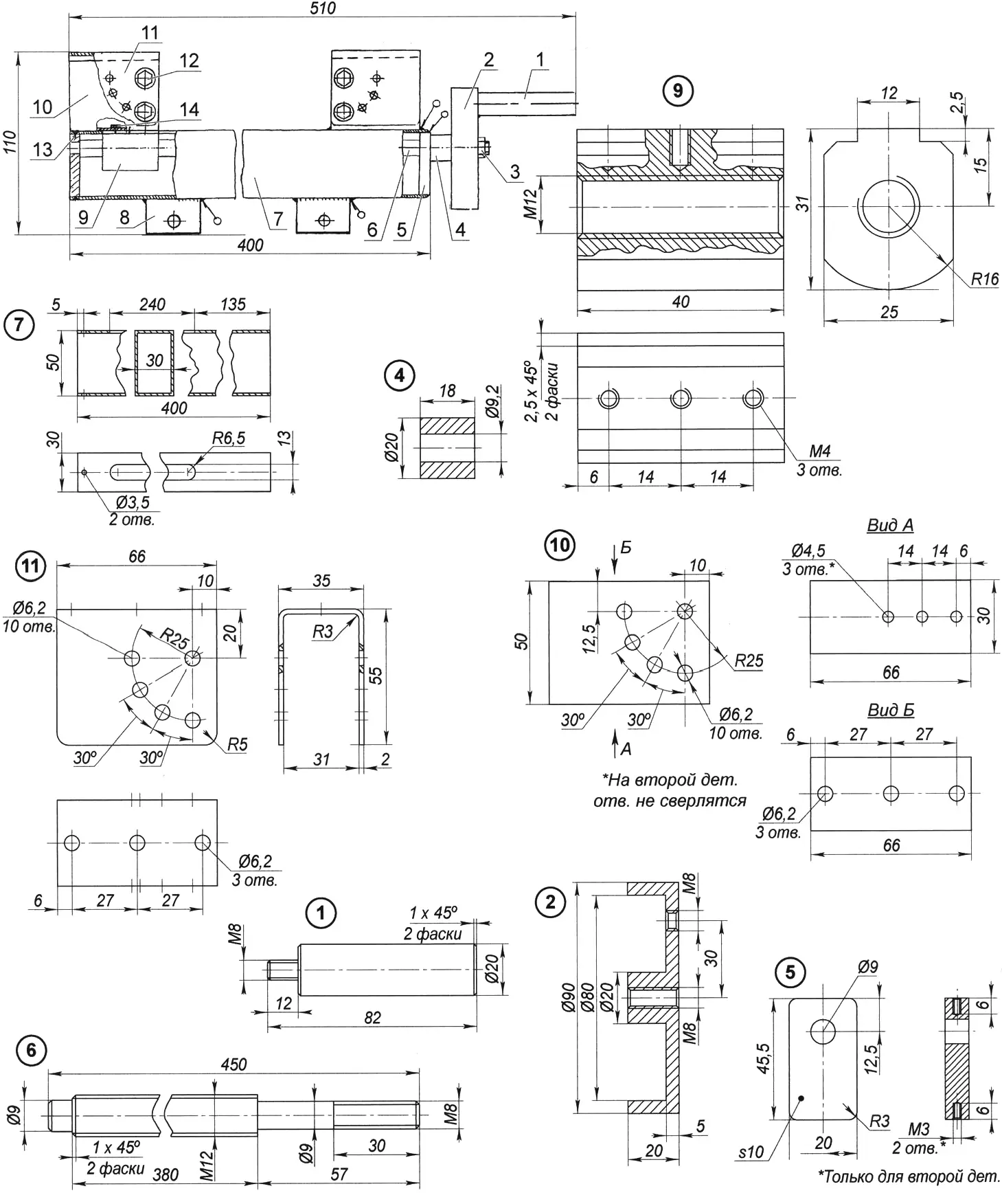
1 — handle (steel, round 20); 2 — handwheel (D16T, round 90); 3 — fastening of the handwheel on the lead screw (M8 nut); 4 — spacer bushing (steel 10, round 20); 5 — lead screw support (steel 10, s10 sheet, 2 pcs.); 6 — lead screw (M12 construction stud); 7 — body (rectangular tube 50x30x2); 8 — leg mounting bracket (steel, s2 sheet, 2 pcs.); 9 — nut (steel 35, round 32); 10 — table base (steel rectangular tube 50x30x2, 2 pcs.); second part — mirror image; 11 — table bracket (steel 10, 2 pcs.); second part — mirror image; 12 — bracket lock (M4 bolt, with washer and nut, 4 sets); 13 — lead screw support lock (M3 screw, 2 pcs.); 14 — fastening of the table base to the nut (M4 screw, 3 pcs.)
Two brackets are welded to the bottom of the body — for connection with its pair of legs. At the top, on one end of the body (on the handwheel side), a base for mounting one of the tables (there are two of them as well) is welded on. The base is made from rectangular tubing 50x30x2 mm. The other base (for the second table) is bolted to the nut with three M4 screws.
The tables are attached to the bases through brackets: one table to a pair of fixed bases, and the other to a pair of movable ones (mounted with M4 screws on the nuts). The tables are attached to the brackets with M6 countersunk-head bolts.
When the movable table is shifted as close as possible to the fixed one, both form a single, fairly large plane.
Together with the tables, the brackets can be set on the bases at fixed angles: 30, 60, and 90 degrees.
Both table tops have a row of evenly spaced holes drilled in them (five pairs along the length). Bosses can be inserted into the holes and attached from below to the table with screws and wide washers. By sliding the movable table toward the fixed one and changing the positions of the bosses, parts and workpieces of various sizes and complex shapes can be clamped on the workbench by compression or spreading, both for gluing and for machining.
“Modelist-Constructor” No. 2’2009, Yu. KURBAKOV
Recommend to read
 BUZZER
Buzzer on digital circuits switching on/off of electronic devices with power supply of 12 V. In the car a lot of devices that are included in the operation key or switch. To control... THE MACHINE “HEARD”…
Most of the machines and mechanisms used in industry, agriculture and the service sector, by themselves, unfortunately, still not working. These mechanisms have to enable, disable,...
