From my own experience I know that after publishing a homemade car in the magazine “Modelist-Konstruktor” (as with mine in the January 1971 issue), authors receive letters from many cities asking them to share their own experience. Now, during the crisis, when the opportunities of amateur builders are as limited as possible, I want to help interested readers with practical advice: how to restore or make a car body by the hammer-forming method.
I gladly do this for everyone who needs such help, especially since the pages of technical magazines still contain almost nothing of the kind that could help an amateur car enthusiast realize his fantasy in metal by hammering sheet metal.
Of course, hammer-forming is in many ways inferior to stamping or panel beating with specialized tools, yet the hammer helps in amateur construction: with it you can make, say, a car fender so well that even an experienced craftsman might doubt it was done exclusively with a hammer.
Imagine the Middle Ages: shields and helmets, knightly armor, plate armor — they were clearly made with nothing other than hammers. And it is strange that in our time people gathered around a homemade car argue among themselves, and sometimes even object to the author that this cannot be done with a hammer and is available only to industrial stamping.
Hammer-forming work requires relatively little equipment — a set of tools and simple fixtures. Much more preliminary thought is required. And my task is to try to help beginners and guide them along the right path.
I will begin with the hammer. Let us consider how a sheet of metal behaves under one blow or another and depending on the shape of the tool’s face. This is visible when making the simplest curved forms. And as is known, the complex consists of simple parts; for example, the not-so-simple shape of a fender is a combination of the same simple figures that will be discussed below.
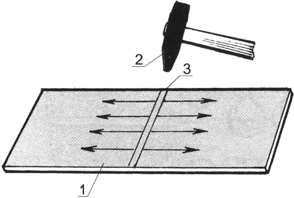
1 — strip; 2 — hammer; 3 — starting line of blows. Arrows here and on other figures show the directions of metal expansion
Figure 1 shows a line of blows across the strip. In this case, stretching of the metal occurs along it. This property is used, for example, when dressing a scythe, where stretching along its blade is unacceptable, otherwise waves will appear on the scythe blade.
By this method you can lengthen a strip, and by striking one side you can bend it into a ring, make a complex decorative facing, and other similar things.
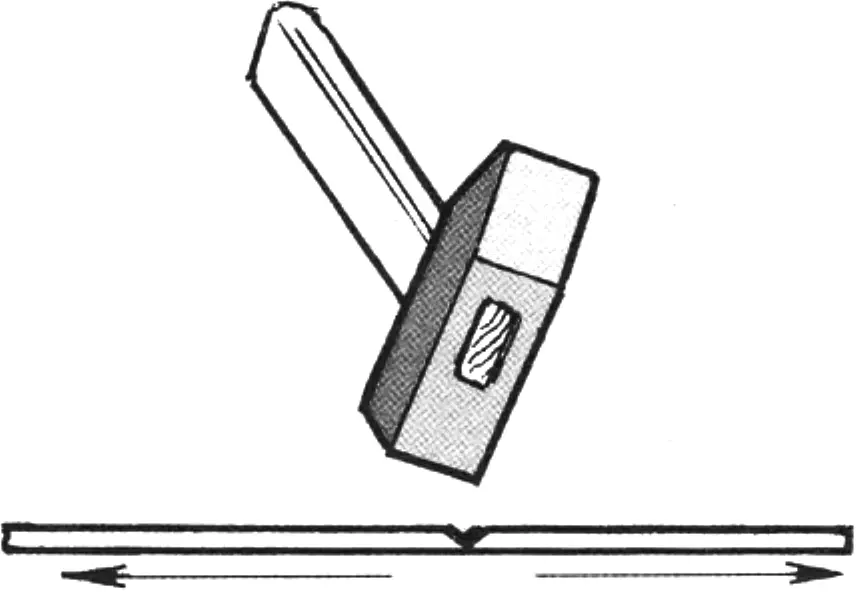
Figure 2 demonstrates the same effect even if the blows are delivered not with the peen but with the side face of a square hammer. A square 500—600 gram hammer proves indispensable here.
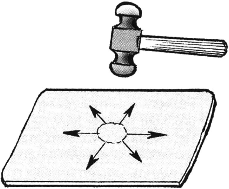
blows are delivered sequentially along an expanding circle
However, tools can have more complex shapes. Figure 3 shows a special coppersmith’s hammer. Blows delivered with it stretch the material radially — from the center of the blank to the periphery. Such a tool is suitable for hammer-forming spherical surfaces — for example, a bowl, a spherical surface, the end section of a bumper. On flat surfaces (a hood) such a hammer will create undesirable bulges and excessive work-hardening of the metal.
In all cases one should strive for the radius of the hammer face to approach the radius of the part.
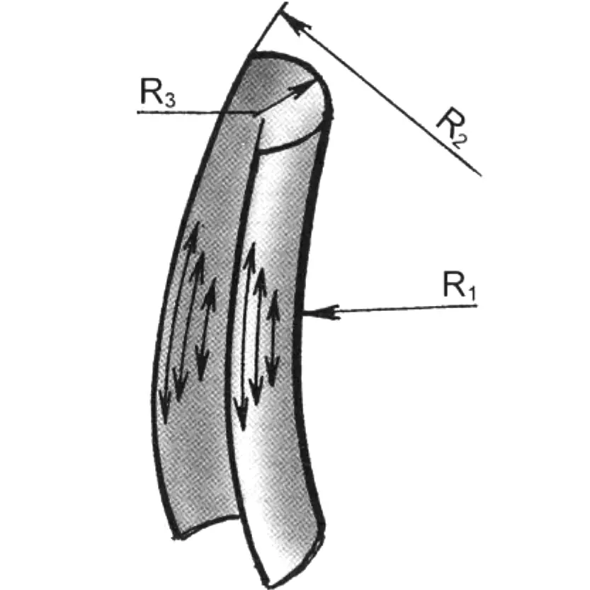
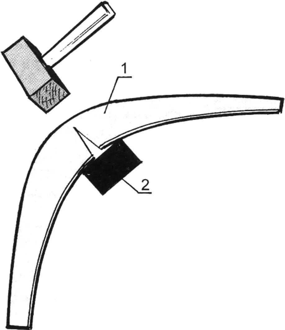
Figure 4 shows the process of obtaining a curved gutter. The length of the arrows symbolizes the degree of metal stretching. When hammer-forming, the flat middle is bent first, with a large curvature (or, in other words, a smaller R3), because when the sides (R2) are stretched it will partially straighten out. The side of the gutter is a large arc, which means it also requires greater stretching, with blows “fading” toward R1. A part such as a mudguard is the same gutter, only curved in the opposite direction (Fig. 5). The blank is bent less, because when stretched along the axis its sides compress. This figure is more labor-intensive, and the metal receives greater work-hardening — the internal structure is disrupted, weakening the material. Therefore one strives for blows, especially with a sharp face, to be weaker and lie closer to one another. In this case all areas of the sheet are subjected to stretching, and thereby the metal is spared from becoming too thin.
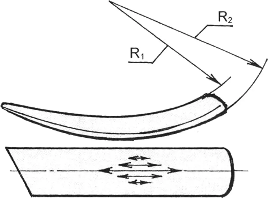
Figure 6 shows the scheme for hammer-forming a “stovepipe” segment (without a bottom). It consists, as it were, of two previously discussed figures. In manufacture a flat blank is taken and hammer-formed with a coppersmith’s hammer on a smooth plate. Then the gutter (lower) part is worked using the techniques considered for figure 4. And thus, moving from one area to another, we watch the shaping of the segment.
Sometimes a part twists. It “flaps” due to internal stress. But one should not be discouraged; instead, continue watching the overall shape, imagining it straightened. Next, areas requiring stretching are “felt out” with hammer blows, and if the part begins to stiffen and curve, that is where one should continue striking. Those with experience will identify such places without “feeling them out.”
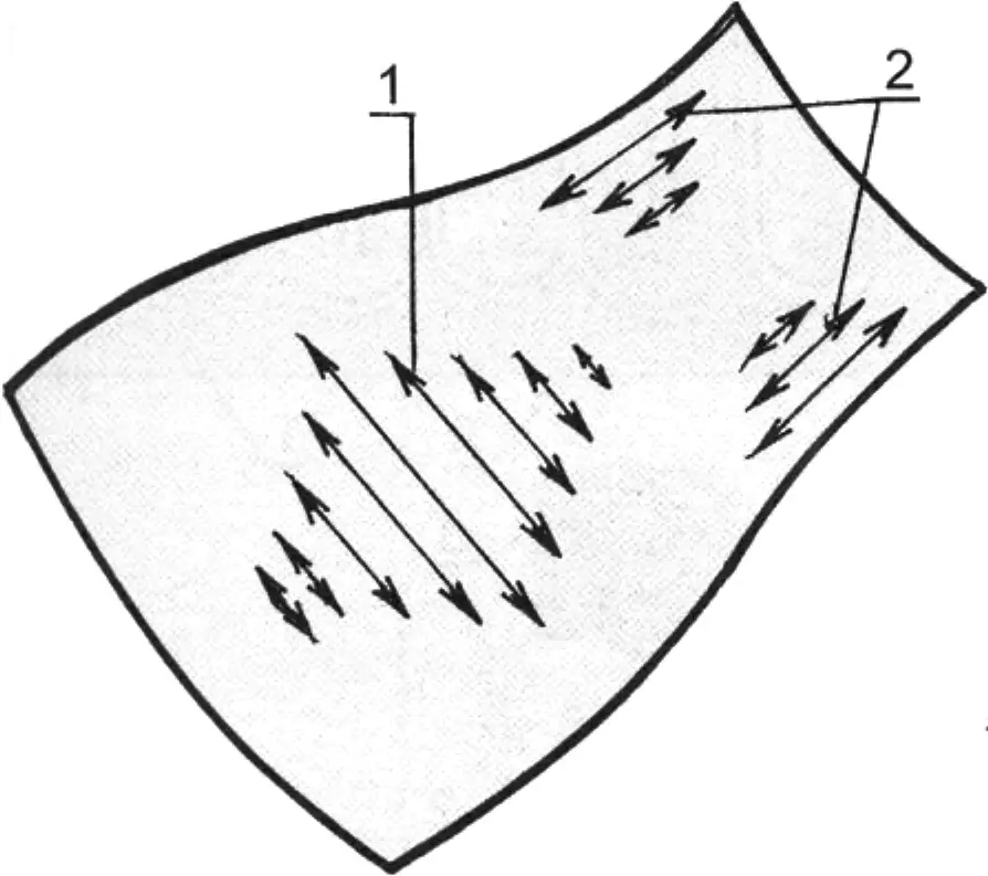
1 — directions of blows for transverse stretching of metal; 2 — the same for longitudinal stretching on both sides
The blanks obtained above require finishing of their face surfaces and mating edges. This is done with a lighter tool; a shoemaker’s hammer can serve for this, with the face side tapped while a dolly is placed on the inside and supported by hand. Any steel block with spherical surfaces and a mass 2—4 times that of the hammer can serve as a dolly.
When bringing an adjacent area flush, it is not necessary to strike from the other side: as it stretches and straightens, supported by the dolly, it comes flush with neighboring areas. Thus the entire form and its face side are finished. This operation is the most responsible. Having mastered it, a person can easily (and very skillfully) straighten, for example, the body surface of a car that has been in an accident.
If the eye cannot detect irregularities during planishing, the surface should be lightly filed with a flat file until these irregularities appear, and then planish again, alternately returning to the preceding operation until a smooth surface is achieved. Finally, file it crosswise.
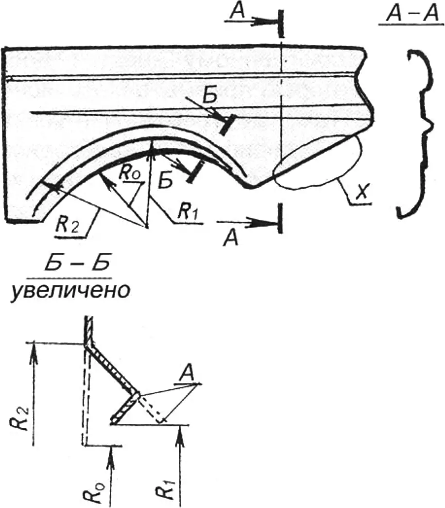
Having considered these basic techniques, let us apply them directly to a car fender. In the fender scheme shown in figure 7, radii R1 and R2 show the flange lines, and section B-B shows its profile, in which radius R0 is the initial one, and R2 is after stretching (since it moved to a larger radius, it had to be stretched).
1 — hood corner; 2 — backing dolly for the hammer-forming period
After this, narrow strip A is “tucked under.” Here partial compression (shrinkage) of the metal occurs. A narrow strip on a large radius shrinks easily; in the wide part or on a small radius the sheet is gathered, as shown in figure 8. The gather is stretched with a sharp face, thereby part of the metal, as it were, goes beyond the form. Element “X” in figure 7 is the shape of the previously discussed “stovepipe” element.
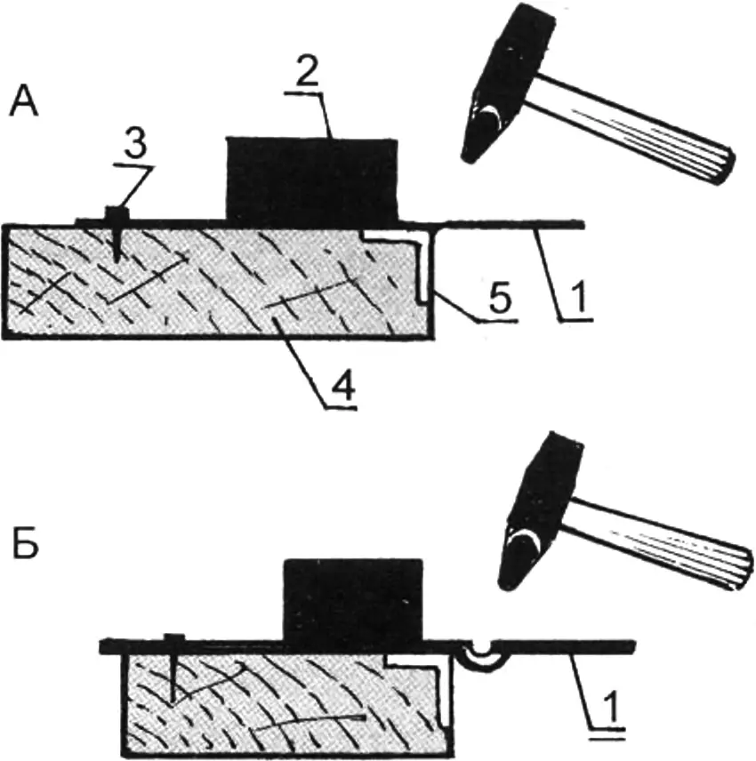
1 — metal sheet; 2 — weight (dolly); 3 — fixing the sheet with a nail; 4 — workbench; 5 — steel angle
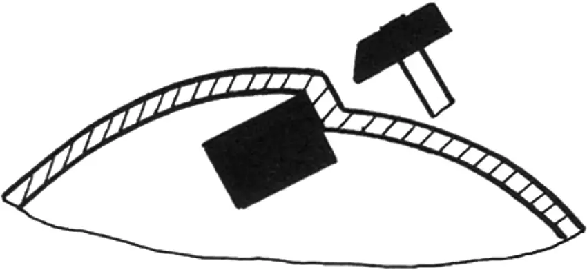
Ribs are hammer-formed with a textolite or wooden (hardwood) hammer (faceted, shaped), as shown in figures 9 and 10. After finishing one side of the rib, the fender is set on the other side. To keep the sheet from shifting, it should be nailed at the corners (or clamped with clamps).
In figure 10 the second rib (angular) is worked with a faceted mallet. It bends without much effort. As shown in the figure, the sheet is slightly bent by hand, and the mallet taps along the very edge of the bend without spreading the blow onto the sheet itself.
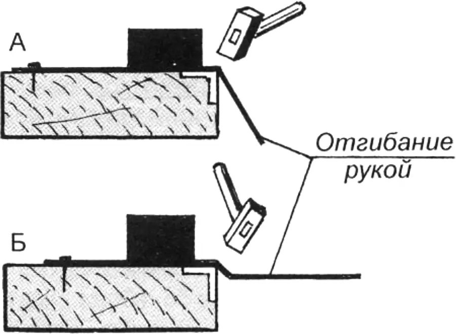
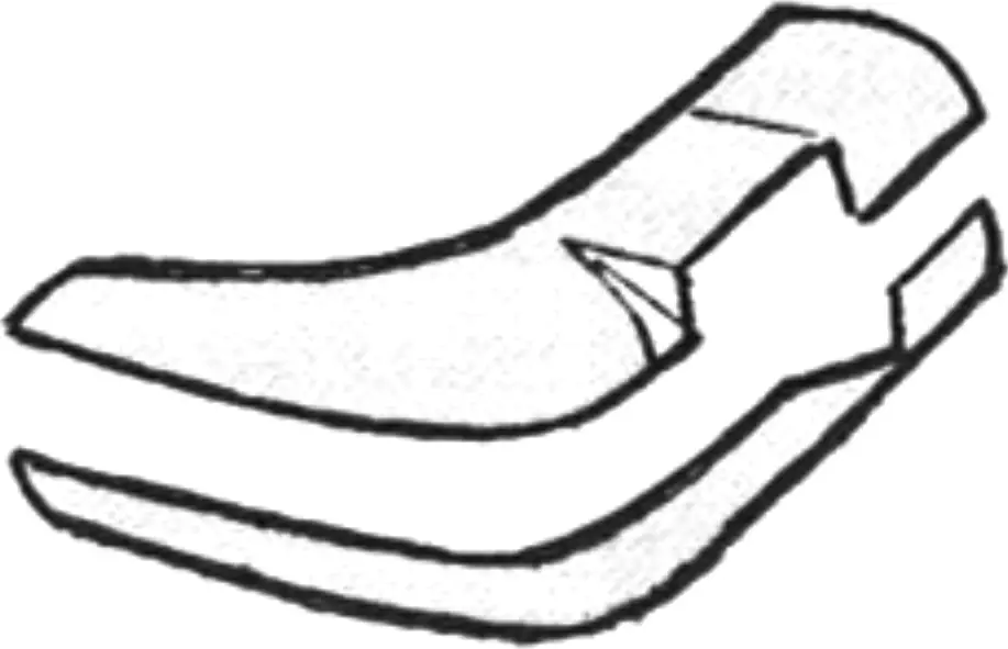
Thus, after passing several times along the edge, the sheet is bent with a sharp edge and angle. Turning the sheet to the other side, the operation is repeated. As a result the blank acquires a strict zigzag, which we see on the fender (section A—A in Fig. 8).
To what has been considered one should add some decorative techniques. Where deep hammer-forming is required, it is convenient (and necessary) to split the part beforehand, as shown in figure 11. Then each half separately is easier to make. They can then be welded or riveted. After riveting the face side of their joint is brought flush (as in Fig. 12) and soldered (putty in such places is unsuitable: it cracks).
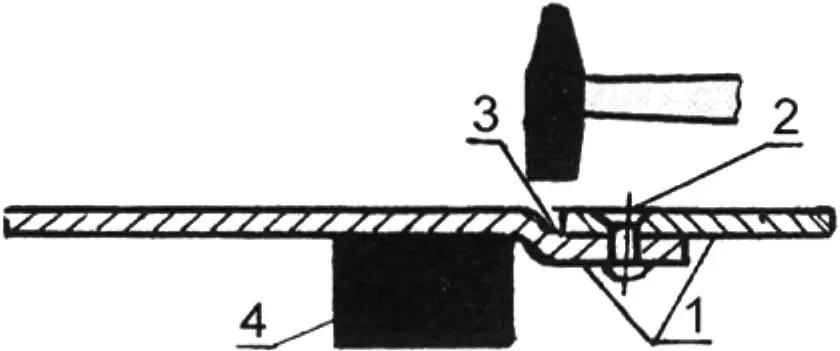
1 — sheets riveted after hammer-forming; 2 — rivet; 3 — soldering; 4 — backing dolly
If ribs need to be marked on a curved or spherical surface, they should be made after obtaining such a surface by the technique shown in figure 13.
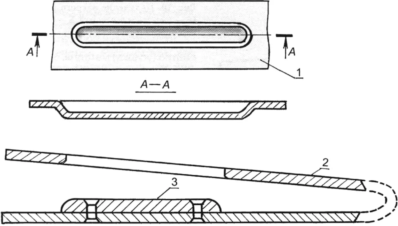
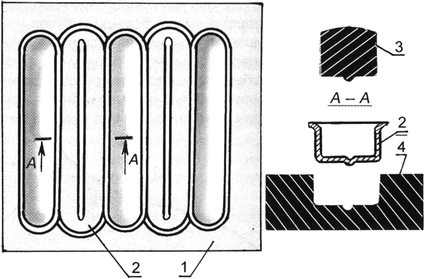
1 — sheet area with a bead; 2 — die; 3 — composite punch
A stiffening bead on a panel is conveniently made with a special fixture, as shown in figure 14. For this, a pair of plates is joined (riveted) at the ends — we get a tool resembling a kind of pincers. In one jaw an opening (die) is prepared beforehand, in the other — a projection (punch); the gap between them equals the thickness of the sheet on which a bead is required. A blow from a light sledgehammer is enough for the panel, caught between the jaws of the fixture, to receive the needed bead.
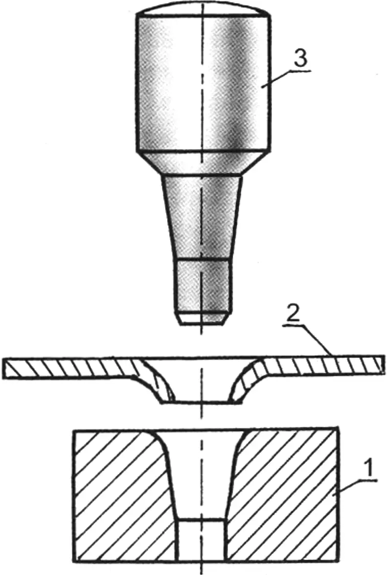
1 — die; 2 — perforated sheet; 3 — punch
To make grilles, a flanging die is required; its scheme is shown in figure 15. Such a die can be made from any steel. Holes in the blank will match the die diameter. Flanged holes are joined by cutting out (Fig. 16) and the bottom of the grille is shaped. Finally, it is advisable to calibrate the holes with mandrels (Fig. 16) and simultaneously press an additional rib between the slots.
1 — sheet of complex configuration; 2 — area of deep bead; 3 — mandrel; 4 — die
These are the techniques with which, in an ordinary shed or garage, one can make individual parts or an entire car body of any desired configuration.
“Modelist-Konstruktor” No. 9’2010, G. VARAKIN
Recommend to read
 ITALIAN FURNITURE
Who does not dream of an exclusive set of Italian furniture, made to order and to your individual drawings? From this can refuse unless a madman. Of course, to afford such luxury can not... AND CHAIR, AND NIGHTSTAND
In small apartments, each square meter not only, as they say, accounting, but is used by the hosts with the maximum load. And that, in General, reasonable. For such housing they try to...
