 Improvised creativity are addicted to for a very long time. And in many respects it was promoted by my favorite magazine “modelist-Konstruktor”. Released since 1972. The recommendations and tips magazine has done a lot useful on the farm structures. The biggest of them —the tractor Arkhipova (“M-K” № 1, 1984), Gromov and all-terrain vehicle (“M-K” No. 1 for 1985).
In this material I want to share with readers one of his hand—lapping machine. 20 years ago, the tinkerers at home to buy such a car was difficult. Now, of course, you can choose to buy a machine for every taste. But… first, the price of “bite” (not everyone can afford), and secondly, what is the true homebrew will go to the store if possible to do all and cost savings, and the design will be such as is necessary for the proposed works.
It took me a relatively small stanochek for processing small parts. Delved into the “modelist-Konstruktor”, but, unfortunately, not found what was needed: the proposed log structures were built mainly on the basis of motor vehicles, and I had a little “diacheck”, which I wanted to use in your machine.
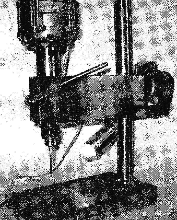
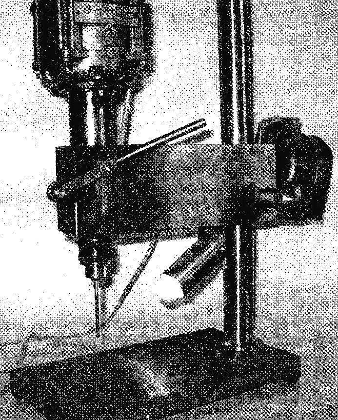
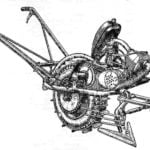
What the result is presented in the photo. To reproduce such designs is not difficult, having some locksmith skills. Difficulties can arise only in the manufacture of several turning parts. If you do not own the specialty Turner, will have to order them.
The basis of the machine—table, the stand and the housing (bracket). The table is heavy steel or cast iron stove. In table 2 there are through holes for fixing racks and storage key Chuck—he was always on hand (this is especially true of the frequent change of drills). The machine table has 4 rubber feet—you can use the corks from bottles of medicine. Using washers the legs are screwed with M4 screws to the bottom plane. Strut serves to vertically move the housing and attached to the table nut M16 clipped by a plane (for the best installation in a vertical position). The body is made from solid cast iron workpiece. It is made of 2 main through hole with a diameter of 28 mm for the stand and a glass spindle. To the glass of the spindle is moved downward at a predetermined distance 42 mm, the case from two sides of the milled slots of the same length and width 6 mm. Middle part of the body with one hand as selected for capacitor start electric motor, toggle switch, voltage indicator and all wiring circuits. The sample in the housing is closed by a plate, which is attached to the housing with M4 screws with countersunk heads. If someone does not like the departure of the cartridge, the machine can have a larger spacing, so that several sizes need to be adjusted accordingly.
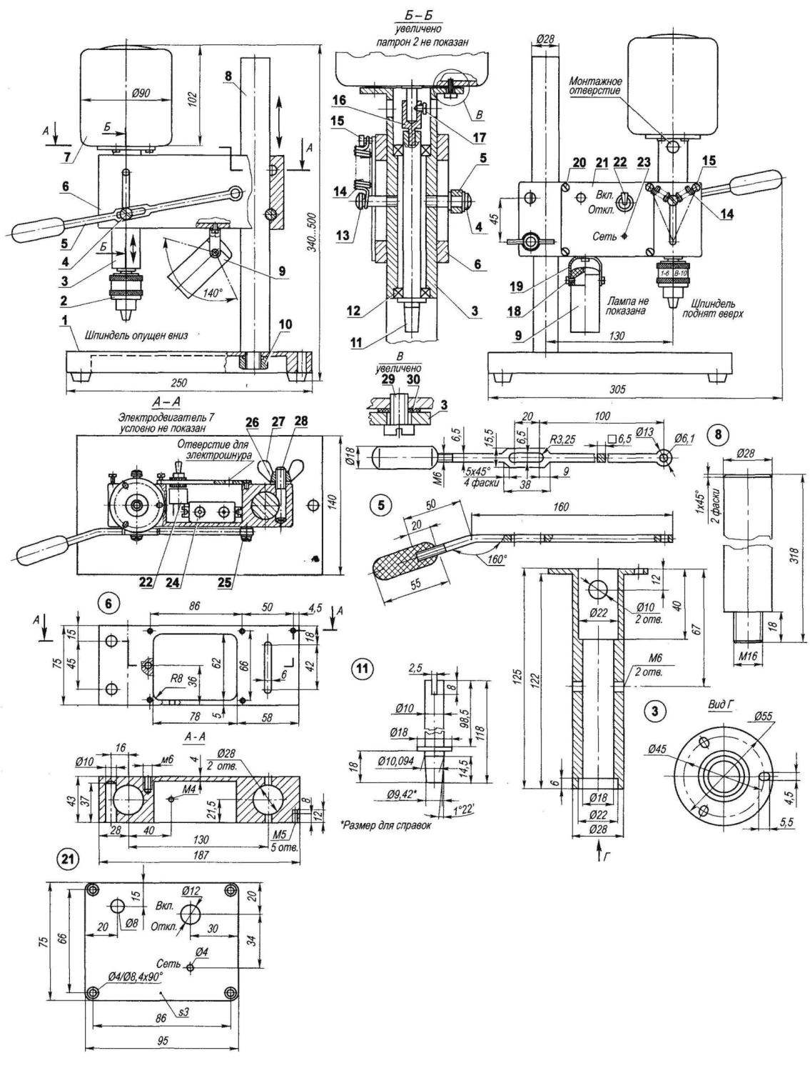
Fig. 1. Table drilling machine:
1—desktop; 2—Chuck; 3—Cup spindle (steel, lap 55); 4—focusing lever (screw M6); 5—lever (steel, strip 6×16); 6—housing (cast iron); 7—motor (KD-50—household appliances, N = 60 W n = 3000 rpm); 8 — front (steel 45, range 30); 9—lighting from a small penlight bulb 220 V); 10—strut (nut M 16); 11 —spindle (steel 45, range 18); 12—bearing 1000900 (2); 13 — movable hook of the spring (screw M6); 14 — spring return spindle (2); 15—fixed hook of the spring (M4 screw, 2 PCs); 16—bushing-coupling (steel, circle 10); 17—mounting the half-coupling (screw M3); 18—the axis of rotation of the ceiling (M4 screw,2 PCs.); 19—bracket ceiling (steel, band 1,2×20); 20—mounting the lid (M4 screw, 3 pieces); 21—a cover (steel, sheet s3); 22 the switch; 23—led; 24—capacitor (4 UF); 25—the axis of the handle feed (screw M6); 26—washer; 27—nut-M10 lamb; 28—latch housing (pin M10); 29—engine mounting (M4 screw, 3 pieces); 30—gasket (rubber s2, 3 PCs.)
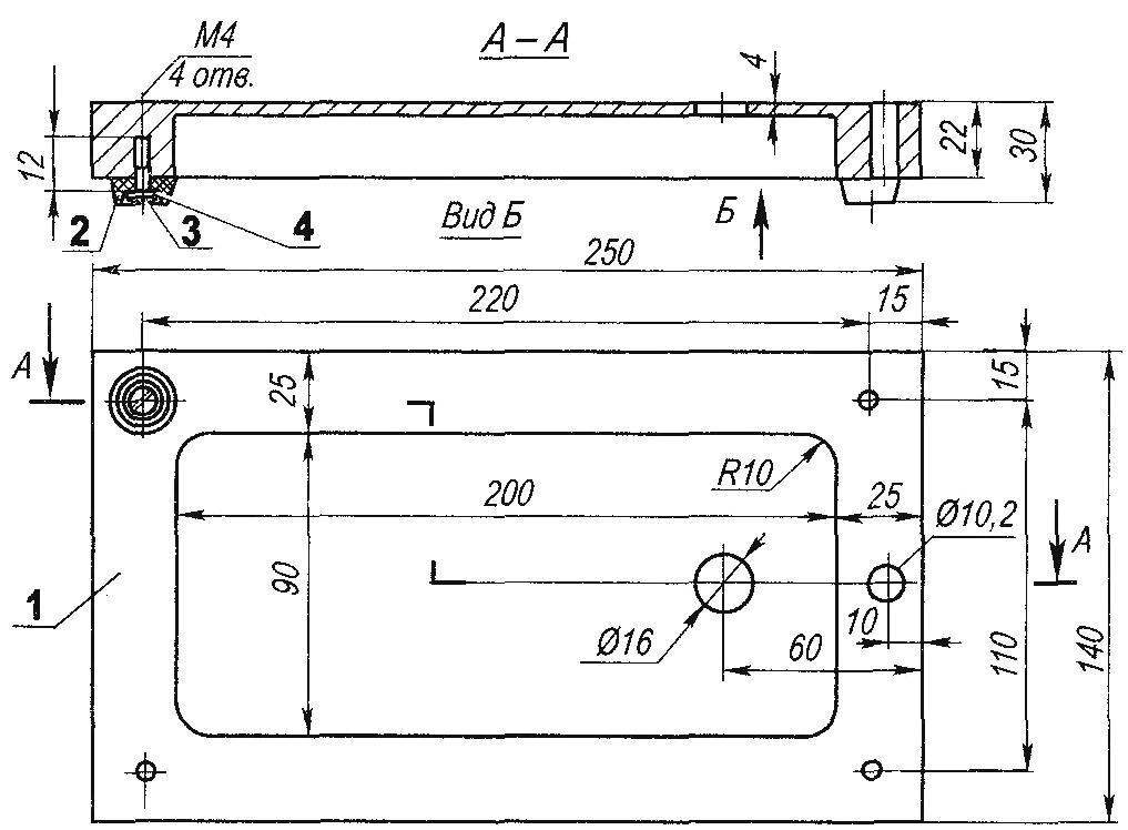
Fig. 2. Desk:
1 —body (steel, iron); 2—rubber leg (4 PCs); 3—fastening of the legs (screw M4, 4 PCs); 4—washer (4 PCs)
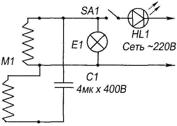
Fig. 3. Wiring table machine
The spindle Cup is mounted on two ball bearings No. 1000900 (10x22x6). Bearings you can pick up and other, preferably closed, slightly modifying the size of the glass. The spindle end has a shortened Morse taper under self-centering Chuck 10. The cartridge provides a fastening tool (drills, core drills, reamers, etc.) with cylindrical shanks with a diameter of 6 mm. If desired, the spindle can be made and chambered for the room above, designed for fastening of the drill to 10 mm, but for drilling steel parts power standard motor will not be enough.
For lubrication of bearings and cups of the spindle is required Litol or ciatim.
Motor KD-50—from appliances selected fairly common: power N = 60 watts, rpm: n = 3000 per minute. It is mounted on a glass spindle 3 rubber rings. Such installation ensures the best shaft alignment. To transmit the torque from the motor to the spindle on the motor shaft is pushed (if not standard) bushing. The lower end of the sleeve has been filed off of the plane, as shown in the figure. Spindle in the upper part has a groove-slot in which to insert the sharpened end of the sleeve. With proper alignment, this transmission should work smoothly.
Stand has a height of 300 mm—for drilling small and oversized items that is enough. In addition, the main body of the machine rotates 360 degrees, and if on the table to set the additional weight, it is easy to drill and high detail, turning the body in the opposite direction. For anchoring and retaining the housing at a given height is the clamp, consisting of studs, flat washers and nuts-lamb. Stud is installed in one of the two blind holes of the housing and ensures a secure fit.
The lever may be carved from bar stock or cut from steel strip and impose on her the handle of the dielectric. In the Central part of the widened handle there is a flat area with an oblong groove. Along the slot moves the body of the screw, screwed in the Cup of the spindle. At the end of the handle drilled a hole for the axis. On the other side of the hull in the vertical groove moves exactly the same M6 screws, which are mounted on two cylindrical return spring spindle. Opposite their ends attached to the screws in the upper part of the body. Instead of springs you can use an elastic rubber band or rubber ring cut from a motorcycle camera.
As for the electrical equipment of the machine, we should pay attention to the presence of a led diode, signaling readiness, and highlight with a small penlight bulb for a voltage of 220 V, which is mounted in a homemade tubular canopy. The attachment of the shade to the arc-bracket with two M4 screws and the arcs to the lamp housing provides sufficient degree of freedom and the extra lighting of the working area, which is especially important when operating small drills.
To give the aesthetic appearance of the machine can be painted (except for the rack, Cup spindle, and the upper surface of the table).
The photos are a slightly modified design of the machine. The differences are not fundamental. One of them is in a different location of the handle feed—me as work has become more convenient. The second is the wing nut I put a massive round pen. The third change—strut to the table with three screws through the flange. The positive effect of this is increasing the rigidity of the connection strut with a table, as the drawback of increasing the size of the workpiece and the complexity of manufacturing the rack. The pictures on the back of the body visible to the console—grinding machine for dressing of drill bits and other tools. Within this publication, this device is not considered.
This product faithfully serve in my workshop for the third decade. All repeating design good luck in the work.
I. ROSTOV, p. Sazonovo-1, Vologda oblast
Recommend to read
 PUSHPULL IN THE GARDEN
In the "M-K" is not just talked about different designs and the complexity of the tillers. They were mostly two-wheeled options. I think that the homebrew in vain underestimate the...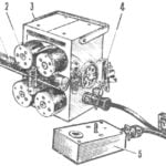 “ELECTROMURES”
The name given to the original device, designed to replace manual labor when laying trunk cables with a diameter up to 60 mm. With their heavy lashes, as if boatmen twine could handle,...
