
 This plane I made, that is, when there’s a rather large amount of work on the harvesting of lumber. During the operation of the tool revealed that he was “tough” even solid wood, and also showed high reliability, comparable with the factory models. Tool performance and quality they planed surfaces, as I expected, was much higher than when processing lumber with hand tools and one.
In General, the planer is quite good, and I decided to share it with the readers of the journal “modelist-Konstruktor”. I think that this tool will find its master that it can do for yourself and Amateur tinkering — the one who often have to plane the wood, and “Domostroy” — who had taken over their construction of their home or cottage.
Getting smooth parts “under the line”, as well as providing them a precise fit and clean planed surfaces allow not only to call this tool electroparka, but to use it as such.
Like most homemade products, the tool is simple in design and made from materials available. The electric motor is taken, of course, ready — vacuum cleaner “Rocket” (capacity 270 W, rotation speed 8000 rpm).
Even better for this purpose went to the motor from a vacuum cleaner Uralets (capacity 370 watt number of revolutions of 15,000 per minute). But the last one I bought later, and for its installation on the instrument would have to change the mount.
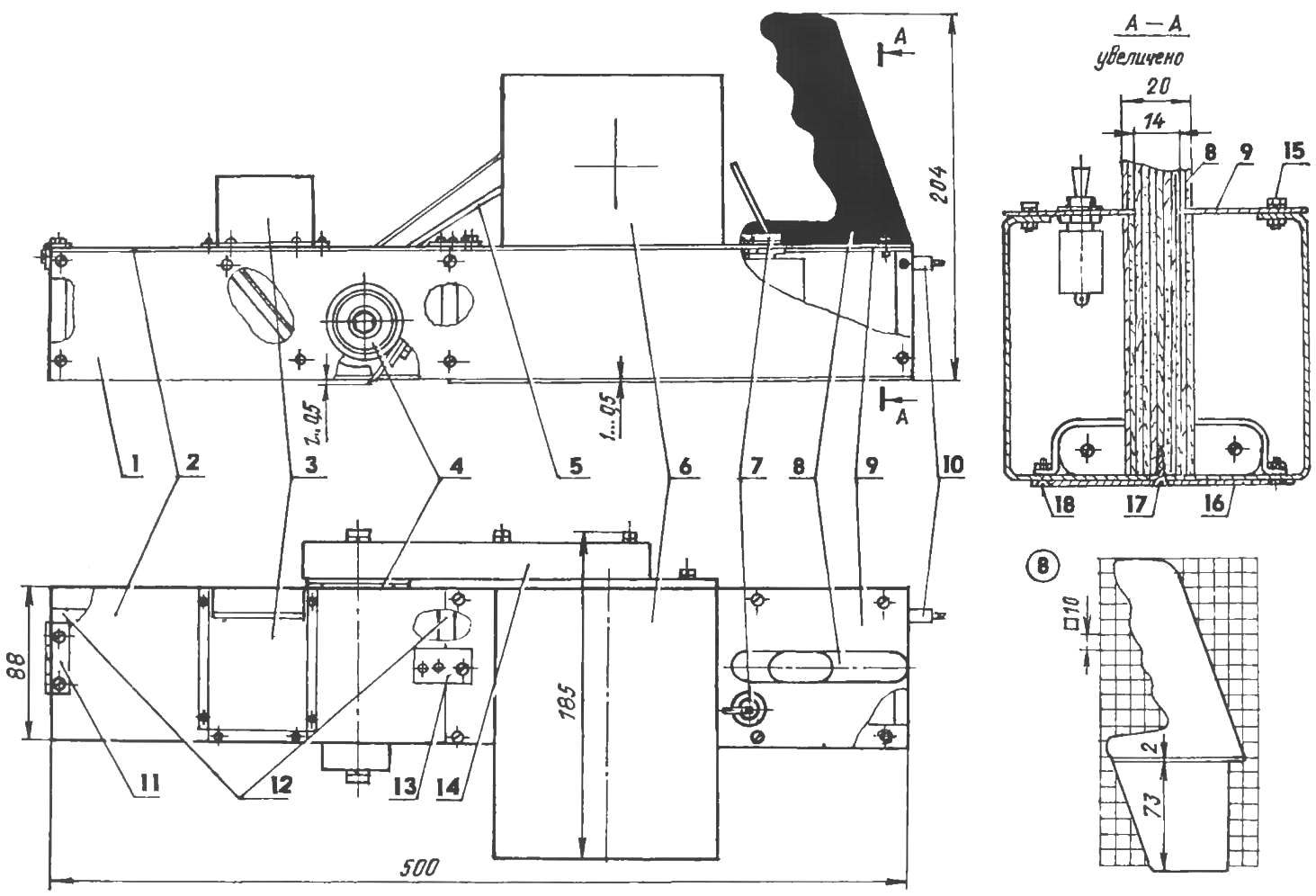
Elektrorubanok:
1 — body (St3, sheet s1); 2 — flip cover (St3. sheet s2); 3 — casing struzhkolomatelja (STZ, sheet s1); 4 — knife node; 5 — drive V-belt (kitchen machine KM 8); 6 — electric motor (a vacuum cleaner “Rocket”); 7 — switch KM-9; 8 — arm (plywood or Micarta 520); 9 — deaf cover (St3, sheet ,s2); 10 — power cord; 11 hinge; 12 — jumper (s8 aluminum, 3 PCs.); 13 — slip clasp flip cover (steel plate s2); 14 — cover drive belts (St3, sheet s1), 15 bolt M3 mounting blank cover (8 PCs); 16 — sole (45 steel, sheet s1); 17 — fastening arm (4×20 screw, 2 PCs.); 18 — mounting sole (bolt M3, 4 PCs.)
Used a few more details of factory manufacturing: two bearing 60202 (suitable 80202) for the cutter shaft and V-belts (kitchen machine KM-9).
Manufacturer of cutter shaft and rotor entrusted to Turner-professional — these parts revolve with high speed (over 10 thousand rpm, depending on engine speed and diameter of pulleys belt transmission) and require not only a good alignment of the material, but if necessary — and careful balancing. The rest of the parts and components produced independently.
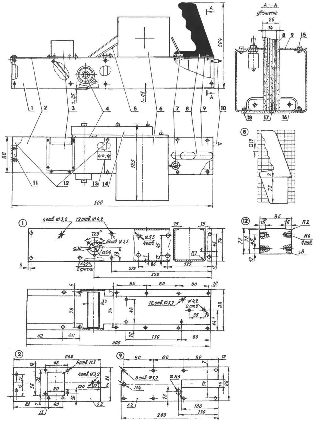
Pad tool — or rather, the body has the traditional shape of the ordinary wooden hand-plane or jointer — rectangular parallelepiped. It is made of steel sheet of 1 mm thickness, hollow inside and therefore very light. To give the body rigidity inside it was strengthened by three 8-mm dural solid jumpers, which the M4 screws with countersunk heads are attached to the sidewalls of the housing (the wall). Top body closed by a composite cover. One part (the front)through an articulated hinge attached to the front of the jumper and can be opened for periodic inspection of blades and cleaning of the cavity of the cutting unit. The other part (back) privernuty bolts M3 to the upper edges of the housing. In the end it has a slot into which grooves is inserted into the handle. Between the handle and the front cover on the side of the rack housing is mounted over the motor.
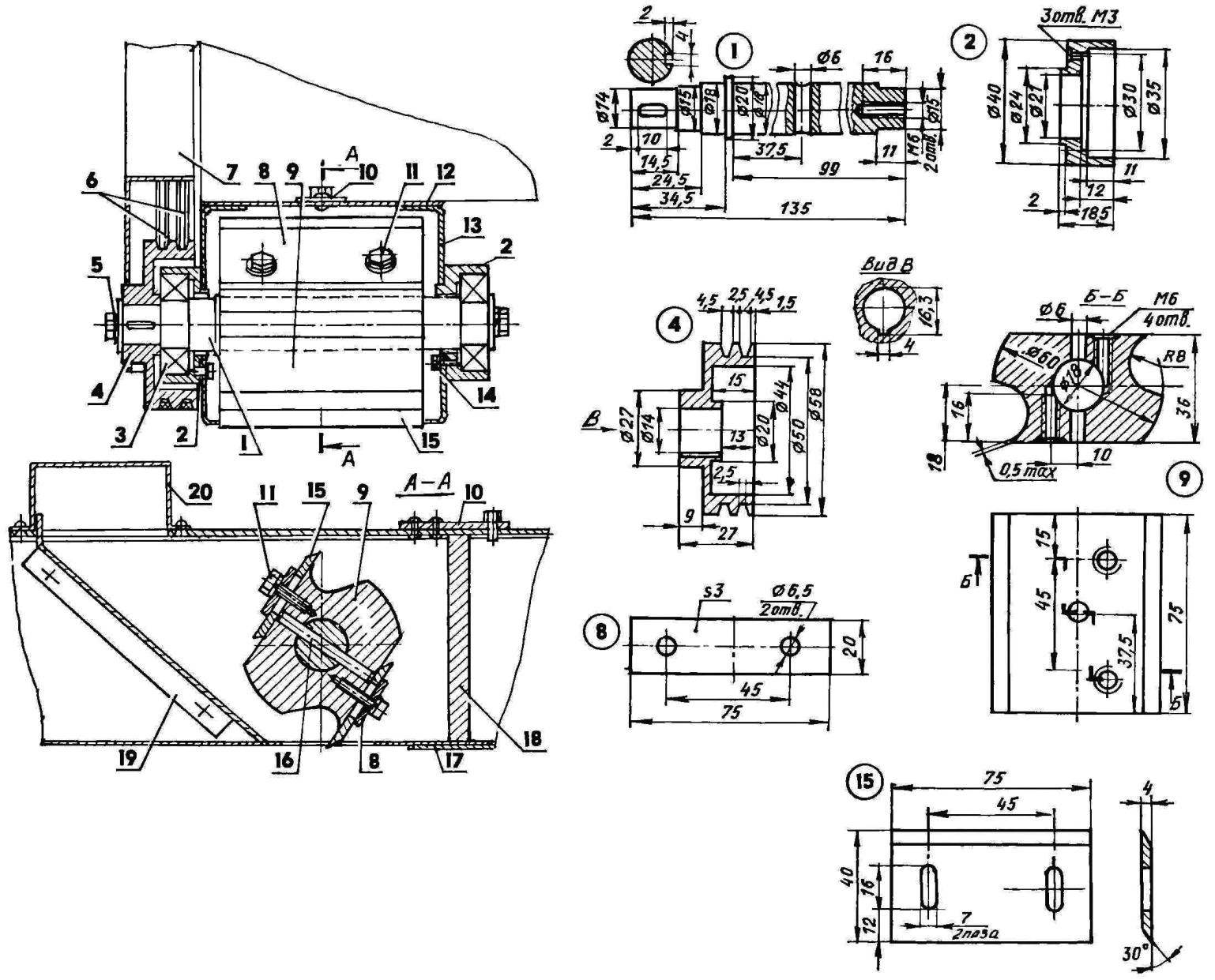
Cutting unit:
1 — shaft (steel 45, range 20); 2 — the bearing housing (steel 45, 2); 3 — bearing 60202 80202, or (2); 4 – driven pulley (duralumin circle Ø58); 5 — screw M6 with washers (2 PC.); 6 — belts; 7 — casing the drive belts (St3, sheet s1); 8 — pressure pads (St3 sheet s3); 9 – rotor (45 steel, round Ø60); 10 – the lock-open cover; 11 – screw M6 washer (4 comp.); 12 is a blank cover (St3, sheet s2); 13 — the case of the planer; 14 – M3 screw with captive washer (6 comp ); 15 — knives (spring steel 65G); 16 pin (St3, rod Ø6) 17 – the plane sole (steel 45, sheet s1); 18 — jumper; 19 — strojmaterialy (St3, sheet s1); 20 — casing struzhkolomatelja
The handle of the plane was cut beech Board with a thickness of 20 mm (but can be made of plywood or the PCB). The dimensions of its root portion to mate with the body of the plane shown in the figure, the handle is better to do “by myself”, along the lines of something comfortable for your hand with another tool.
Close handle installed switch so that it was easy to reach with your fingers without removing the hands from the handle. To protect the network from interference from a plane, inside the enclosure front handles installed and secured with clamp capacitive filter from the vacuum cleaner “Rocket”.
Before the cutter drum inside the body of the plane for the chip is done and attached to the side walls of the inclined platform, which brings the chip to a rectangular window in the front cover. To the chips was moved aside, and flew up above the installed window casing.
Cutting unit of the plane consists of a drive shaft, rotor and knife paintings with clamping plates. The shaft is mounted in two bearings 60202, which is fixed on a side wall planer with three M3 screws with spring washers. A rotor mounted on a shaft and fixed by steel 6 mm cylindrical pin through matching holes in both parts.
Blade bars made of spring steel 65G. They are double-edged — sharpened on two opposite edges: when the blunt blade with one hand, knives can be reinstalled by changing their cutting edges. For fastening of knife paintings on the rotor they made holes-grooves for adjustment; through them the knives are attached with M6 screws with clamping plates.
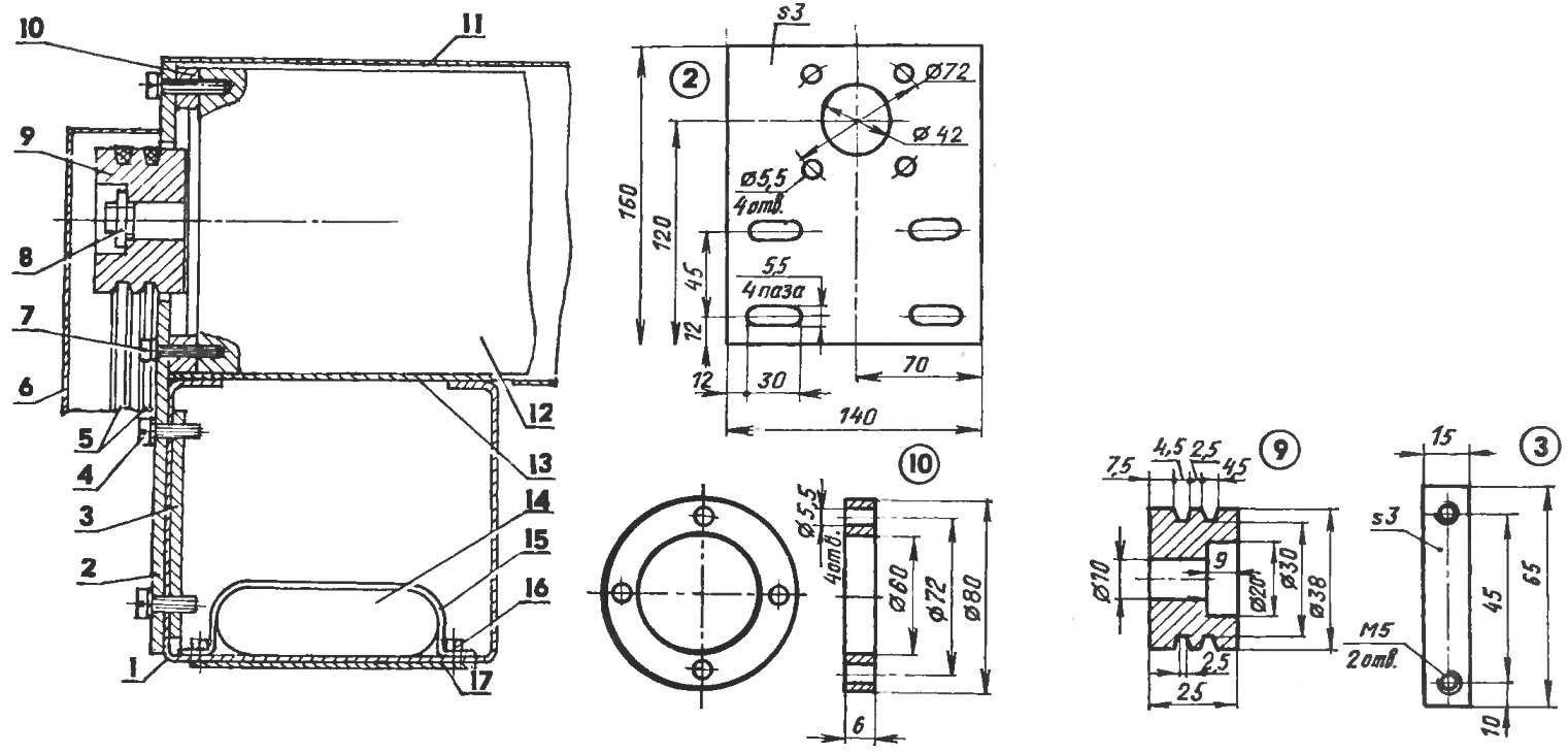
The location of the actuator on the body:
1 — housing; 2 — front (St3 sheet s3); 3 — trim (St3 sheet s3); 4 — M5 screw (4 PCs); 5 — driving belts; 6 — drive casing; 7 – the screw М5х20 (4 PCs); 8 — M10 nut fixing the pulley; 9 — drive pulley (made of anodized aluminum, round Ø38); 10 – spacer (aluminum, sheet s6); 11 — motor housing (steel sheet sl); 12 — motor; 13 — a blind housing cover; 14 — the network filter (a vacuum cleaner “Rocket”); 15 — a clamp filter (steel plate sl); 16 — M3 screw (2 PCs.); 17 — the plane sole
The rotation shaft is effected via V-belt transmission, which is due to the difference of diameters of the driven and driving pulleys greatly increases the number of revolutions transmitted from the electric motor.
And the last part — the sole is mounted on the bottom face of the plane in the rear part. Its thickness of 1 mm (corresponding to an average thickness of a removed shaving). Sole ensures parallel position of the tool relative to the treated lumber, thus allowing the plane to perform the functions of a jointer.
Planing depth can be adjusted by moving the knives in the slots. Its optimal value is about 0.5 mm.
Practice tells us that it is better two times to pass along the work surface with a small depth of cut, than one time with the maximum of the surface is much cleaner, without scratches and chips.
L. SEVIC, Minsk, Belarus
Recommend to read
 PROTECTION TAPE
If you stick to the glass electronic clock transparent sticky film type "Scotch" or used for pasting of books, it will increase the life of the glass and protect it from scratches. ... AERODYNAMICS — TO THE CARBURETOR!
Few car owners do not try to improve their consumer qualities. The most extensive field of activity for auto-rationalizers is the power plant. From time to time, publications appear...
