Most amateur constructors are constrained not only in space (usually they have only a small corner in their apartment for pursuing their favorite hobby), but also in time (they can dedicate themselves to this only late in the evening or early in the morning, when all household members are asleep). Some work can be done quietly, but an operation such as drilling holes is associated with considerable noise, and it is mainly produced by the drill’s gearbox, both electric and manual, although often high cutting speeds and tool power are not required.
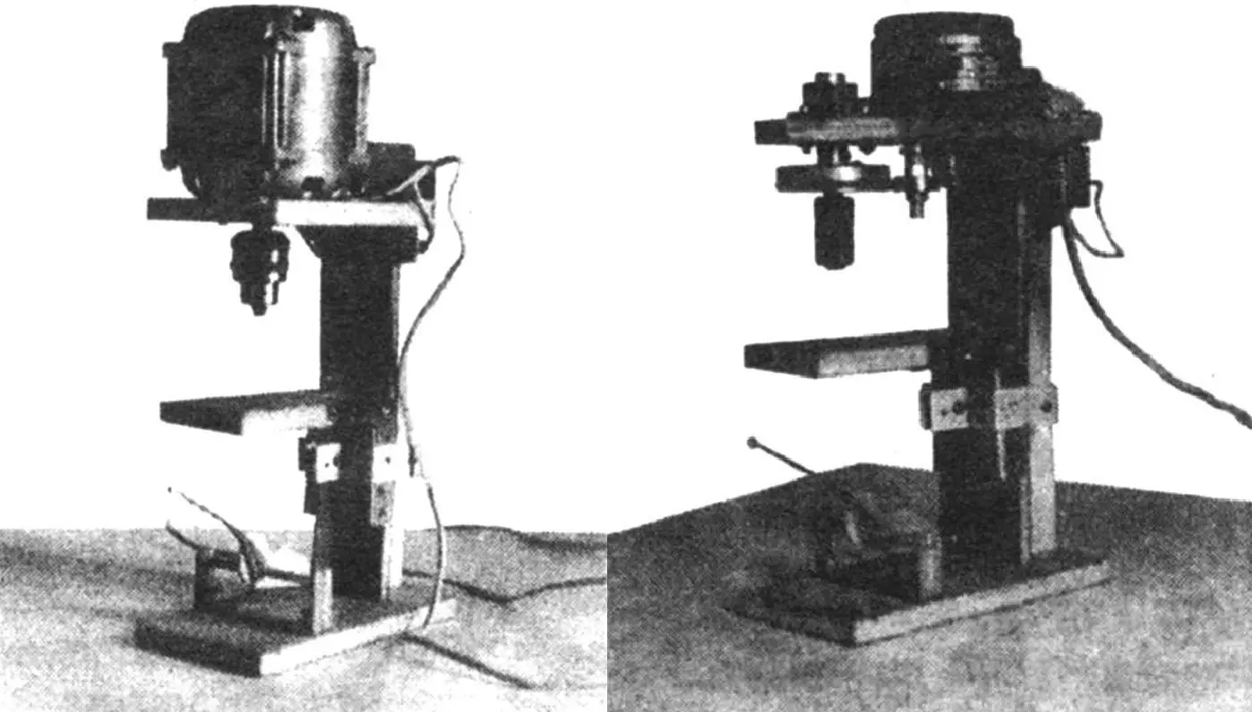
These circumstances prompted me to make a small benchtop drilling machine.
The mini-machine consists of a base, a column, a table with a lifting mechanism, a console spindle platform, and the spindle itself with a drive.
The main material for making the machine bed was plywood sheets of various thicknesses. Thus, the base and spindle console are made of 20 mm thick plywood with the same plan dimensions—180×90 mm. The 230 mm high column is also made from 10 mm plywood strips, consisting of a 50 mm wide shelf and a 40 mm wide rib. The elements, connected to each other with glue and countersunk screws, form a T-section, which provides the necessary rigidity to the entire bed. The base and spindle console are attached to the ends of the column in the same way, and the connections are additionally reinforced with sections of 20×20 mm aluminum angle, fastened with screws. The front side of the shelf is faced with plastic so that the lifting table’s slider slides better on it. A 3 mm duralumin plate measuring 140×50 mm is attached to its rear part, at equal distances from the bottom and top, serving as a rolling surface for the support rollers when moving the table. In the middle part of the column’s rib, adjacent to the shelf, a groove is made for the passage of the support rollers’ axis when raising and lowering the table, and at the edges of the groove—small recesses for the plate.
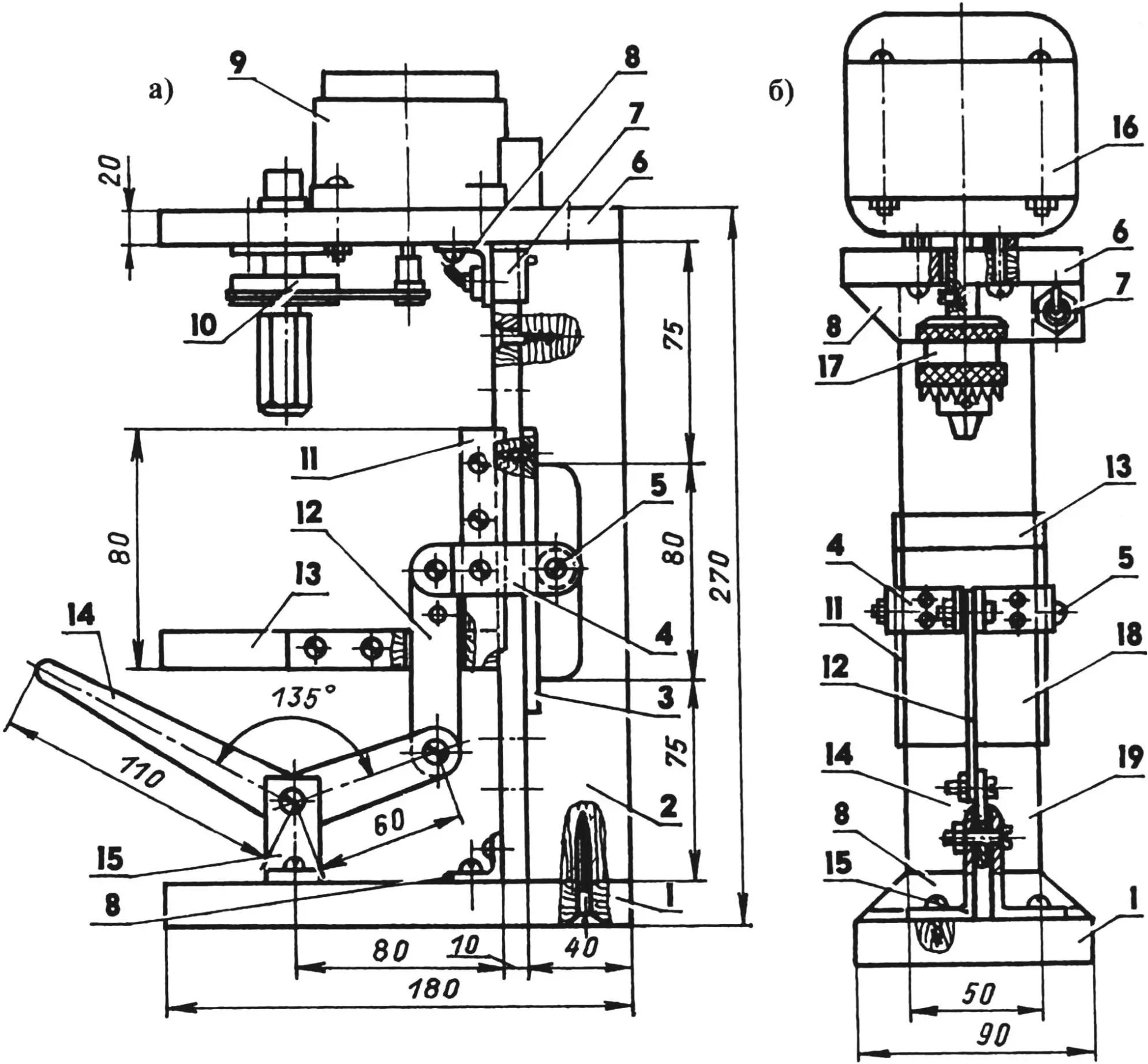
1 — base (plywood s20); 2 — rib (plywood s10); 3 — plate (duralumin, sheet 140×50, s3); 4 — Z-shaped bracket halves (aluminum, sheet s3); 5 — axis with support rollers (M4 bolt with two 23 bearings); 6 — spindle console (plywood s20); 7 — switch; 8 — reinforcement (aluminum, 20×20 angle); 9 — RD-09 electric motor (from “Daina” tape recorder); 10 — spindle unit; 11 — brackets (steel, sheet s2, 2 pcs.); 12 — connecting rod (steel, sheet s2); 13 — work platform (plywood s12); 14 — lever (steel, sheet s2); 15 — supports (aluminum, 40×40 angle); 16 — KD-25 electric motor; 17 — three-jaw chuck; 18 — slider; 19 — shelf (plywood s10)
Lifting table parts: the slider with plan dimensions of 80×50 mm and the work platform—130×60 mm are made of 12 mm thick plywood, connected to each other with a mortise and tenon joint using glue and additionally fastened on the sides with brackets made from 2 mm steel plate and screws. The edges of the brackets protrude slightly relative to the rear plane of the slider and serve as guides for the table when it moves along the column. Overlay brackets here can also be factory-made—those used to reinforce window frames.
The lifting table is held and moved on the column using a pair of support rollers—series 23 ball bearings, located behind the shelf on a common axis and fixed against axial displacement with spacer bushings with the appropriate internal diameter. Here, one could get by with a single roller installed in the middle of the axis, but then it would need to be wider. The axis is inserted into the holes of the rear ends of the Z-shaped bracket halves, screwed to the table slider with screws. Gaps between the slider and shelf are eliminated with spacers between the bracket and slider.
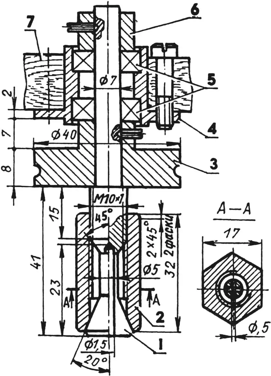
1 — collet (brass LS59); 2 — clamping nut (steel 20); 3 — driven pulley (aluminum); 4 — bearing housing; 5 — 27 bearings; 6 — bushing (aluminum); 7 — console (plywood s20)
The bracket is hingedly connected to the table lifting mechanism’s lever via a connecting rod. The lever is mounted on the support axis, which is rigidly attached to the base. All axes are M4 bolts with threads only on the end. The connecting rod is made from 2 mm thick steel sheet, with an M4 thread cut in its lower hole, into which the axis-bolt is screwed when connecting with the lever and fixed with a nut. The support with lever were selected ready-made, but they are not difficult to make yourself: the lever—from the same material as the connecting rod, the support—from a pair of sections of 40×40 mm duralumin angle, slightly shortening its lower shelf, and as the axis use, as in other connections, an M4 bolt.
Due to the fact that the lever mechanism provides a relatively small vertical travel of the table, the machine design provides for two working positions of the table: with the upper position of the platform relative to the slider or with the lower one. To set it to the lower position, a 20×3 mm slot is made in the platform itself along the axis of symmetry near the slider for the passage of the connecting rod. To set the platform to a third, intermediate position, an additional hole for the bracket axis is made in the connecting rod.
When working on the machine, I use two variants of the spindle unit. In the first variant, when it is required to drill small holes with a diameter of 1.0—1.5 mm, I use a homemade collet made from LS59 brass for clamping the drill. Unlike similar standard devices, in which the clamping sleeve is usually divided into three sectors, mine is cut into four. This is much simpler technologically: one needs to drill an axial hole and make two mutually perpendicular cuts strictly along the axis. The operation is best performed on a horizontal milling machine, but it can also be sawn manually—with a hacksaw.
The spindle with collet is driven in rotation by the RD-09 motor through a reducing belt drive with pulleys from the “Daina” tape recorder. To prevent the belt from slipping under relatively high loads, a tension roller—a series 26 ball bearing with an outer diameter of 19 mm (not shown in the drawing)—is mounted between the pulleys. For this, I insert an axis (M6 bolt) from above into the console hole, and from below I put a spacer bushing with a bearing on it and secure them with a nut.
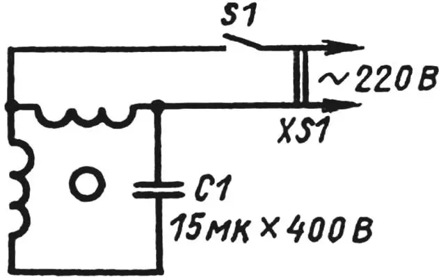
The RD-09 electric motor is designed to operate from an alternating current network with a voltage of 127 V, however, if it is connected according to the given diagram, it reliably operates from a 220 V network as well. In the absence of such a motor, one can use EDG-type motors from a gramophone player or “Kometa” tape recorder.
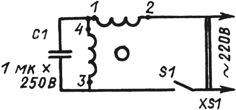
In the second variant, I use a more powerful KD-25 type electric motor in the spindle unit, on whose shaft I mount a standard three-jaw chuck, designed for clamping drills up to 6 mm in diameter, using an adapter bushing. The motor is secured to the spindle console with M4 screws using spacer bushings (M5 nuts), ensuring unobstructed air passage for its cooling. The KD-25 motor connection diagram is shown in the figure. The working capacitor should be covered with a housing, and the wiring connections should be insulated. One can also use tape recorder motors KD-3.5, KD-6-4, AD-5, and others with a power of 25—40 W. Some of these motors operate at a supply voltage of 127 V, but here too there is a possibility to do without a step-down transformer by applying the RD-09 connection diagram. Before installing the motor, one should check whether the shaft has a support that fixes it against displacement in the axial direction, since during drilling it experiences axial force. In the absence of a support, a ball with a diameter of 3—4 mm should be installed at the end of the motor shaft.
Long-term operation of the machine has shown that it can be used not only as a drilling machine. The sufficient power of the second variant’s motor allows adapting the machine for turning work by securing it to a workbench on the side faces of the base and spindle console. Small metal or plastic parts clamped in the chuck can be processed with files and needle files. Thin axial holes in materials such as brass are successfully drilled with a spade drill made from a guitar string with a flattened and sharpened end. In this way, I managed, for example, to make an idle jet for a VAZ carburetor. If, however, the table and lifting device are removed from the machine, and the base and spindle console are connected at the front with an angle (or even a rail), which becomes an improvised tool rest for the cutter, and a lead screw with a pointed end, serving as a tailstock, is installed on the base coaxially with the spindle unit, then the machine can also be used for small turning work on wood.
A. NIZOVTSEV
Recommend to read
 NO BUTTONS, NO SWITCHES
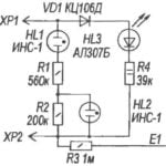
The proposed indicator allows you to capture voltage of 6 — 12V (i.e., below the ignition of the neon lamp) and above. In contrast to the known similar kind of indicators, there are no... RECHARGEABLE BATTERY
Sealed alkaline nucleotidase (NiCd) and Nickel-metallgidridnye (NiMH) batteries are finding increasing application not only in industrial devices but also in home appliances, replacing...
