Mixer need not everyone. But it will certainly be interested in one who wants to build anything on the plot or is already building. The design of the proposed mixer is simple and available for review. It applied quite common components and parts. However, you can collect from other scrap materials, and published a description here as an example.
Mixer (Fig. 1) consists of frame, rotary device, motor, reducer, the tub with the axle and the ground.
Frame (Fig. 2) collected from inch pipes and corners. Below it is attached the axis of the wheels — a solid steel rod, Ø 43 mm, the ends of which turned up to Ø 41,5 mm. are placed Here, for example, worn rollers, crawler tractor. From falling of the wheel kept the wire pins Ø 6 mm in the Front under the base carrier is the heel — the third point of support of concrete mixer. Crowns the triangle of the frame is M-shaped design — a bed for the turntable. At its edges — the two rings-bearing with an inner Ø of 62 mm. and parts of the frame, the axle and the heel are attached by welding.
PA the front left corner-brace welded loop fastener restrictive chains (on her appointment, below), and in the front horizontal area of the drilled hole to connect the wires coming from the ground.
The turning device (Fig. 3) designed for tipping buckets and discharge of the concrete. It is assembled from two pipes Ø 60 mm, bearing housings, the two parts of the ribs, two stops, tipping handle and plugs. Connect all of these parts by welding. Back stop, the handle and end cap are welded after turning the device will be installed in the ring-bearings of the frame. Then it can rotate in the rings, not the advancing of them. Captures the turning device in the working position of wire pin Ø 8 mm. For him and the front ring is drilled (with a tube rotator) vertical diametrical hole.
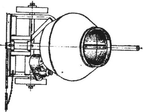
Fig. 1. General view of concrete mixer:
1 — frame, 2 — pin locking swivel device, 3 — rotary device, 4 — motor, 5 — reducer, 6 — drive gear, 7 — bucket, 8 — wheel, 9 — pin wheel, 10 — ground, 11 — restrictive I chain, 12 — mount engine, 13 — driving wheel, 14-belt 15, and driven pulley, 16 — bolt tensioning.
Fig. 2. Frame:
1 — there are struts, 2 — front area, 3 — front ring-bearing, 4 — rear ring-bearing, 5 — the back brace, 6 — axle, 7 — foot, 8 — pen carrier.
By the end of the tipping handle is also welded on the loop connected to the other end of the restrictive chain.
The bearing housing is machined from thick-walled steel pipe. There are ball bearings No. 206 and No. 207 held by the spring thrust washers and shaft buckets, machined from forgings. In the bottom of the bucket making the hole where the shaft is inserted and fastened by means of two profiled washers and nuts. In bearings it is held also by a nut screwed on the shank.
Bucket (Fig. 4) is welded of five elements: the base (you can use any concave disc) with two conical surfaces on polutoratysyachnogo steel sheet, rings of the shell, enhancing the entrance and the ring gear (flywheel end of the engine GAZ-51). Inside the buckets riveted three blades, mixing concrete. They are made of parts, curved respectively to the internal contours of the bucket.
A few words about the engine and gearbox. In the design of mixers applied to the motor, pulleys, V-belt and push-button switch without protective thermal rømø against dilapidated washing machine (see Fig. 1). The motor is fastened to the steering device at the place with steel bands (one end of the strip is bolted to the motor, and the other is welded to the pipe rotator).
On the other side of the motor at four points (two on each of its ends) is fixed to the housing intermediate roller is the main parts of the gearbox (Fig. 5). And the holes in the corners of the mounts are different: two cylindrical and two arcuate, with the help of adjustable tension V-belt on the pulleys of the motor and the intermediate roller. The roller rotates in two bearings No. 202 seated in the housing, and the other end is equipped with gear from the starter GAZ-51.
Fig. 3. Rotary device:
1 — tubular base, 2 bearing housing, 3 — rib, 4 — stops 5— handle, 6 — stopper, 7 — shaft buckets, 8 — shaped washers.
Fig. 4. Bucket:
1 — convex bottom plate 2 — ring gear 3 — body buckets, 4 — ring-shell, 5 — blade, 6 — hole for the shaft.
Fig. 5. Gear:
1 — housing 2 — intermediate roller, 3 — mount, 4 — lug.
The housing has a lug, which are inserted in bolt preload: moving the lug nuts on the bolt, you can increase or decrease the pressing of the starter pinion in a gear wreath of a bucket. Another cocec bolt welded to the bearing housing of the turntable.
Ready to work cement mixer loads through the intake of necessary components: sand, cement, water, other additives, and include an electric motor. During the rotation by the friction-stir mass on the walls of the buckets, the formation of static electricity, which will be given in the ground using temporary ground is a metal stake with a conductor connected to the frame.
When the concrete is ready, turn off the motor and waiting for the spot badic tipping it by the handle. From excessive tipping protects the bounding chain.
T. MEKSICKI
Recommend to read ABOUT VANT-POTENSAC AGAIN In the manufacture of sailboats on a small scale a lot of work goes into the production of the most likely guys-putenkov. A method of simplified simulate these parts and nosing integral... CLAMP? READY! A simple clamp can be made from a long bolt, washers and nuts-lamb. The jaw faces are made of solid wood. 
 Mixer need not everyone. But it will certainly be interested in one who wants to build anything on the plot or is already building. The design of the proposed mixer is simple and available for review. It applied quite common components and parts. However, you can collect from other scrap materials, and published a description here as an example.