The concrete mixer is designed to produce concrete mix or cement-sand mortar. Its volumetric output is 15 ten‑liter buckets of mix in the ratio: 1.5 buckets of cement + 4.5 buckets of sand + 9 buckets of crushed stone (water not included) per batch, with a cycle time of 15 minutes (5 minutes each for loading, mixing, and unloading).
Structurally, the concrete mixer consists of three units: the drum (mixing tank), the suspended cradle, and the frame.
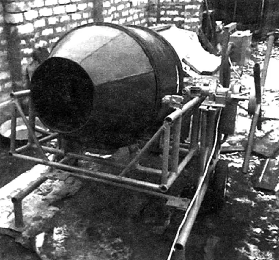
The mixer drum is made of three parts: a cylinder and two truncated cones. Through the front, longer cone, cement, sand, and aggregate are loaded and the finished mix is discharged. The short cone at the rear, to which the mechanical drive is attached, is used directly for mixing the concrete. The material is 3 mm thick steel sheet; the welded structure has a diameter of up to 630 mm.
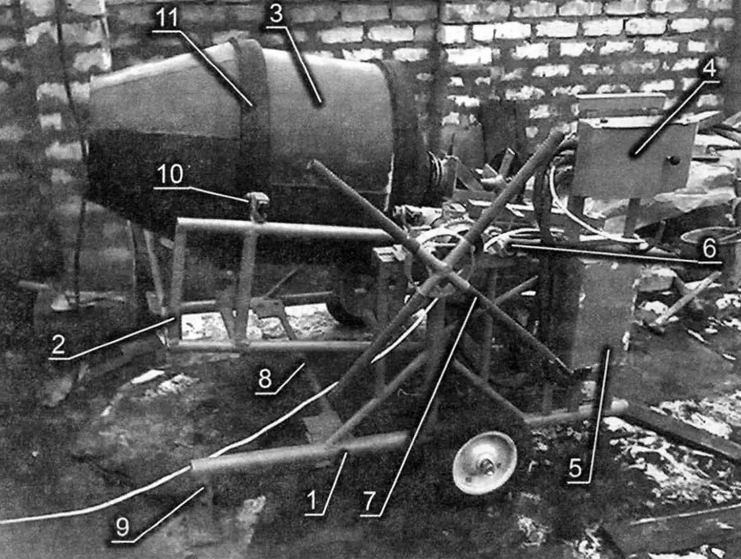
1 – frame; 2 – suspended cradle; 3 – mixing drum; 4 – housing of start button and reverse switch; 5 – capacitor bank housing; 6 – latch; 7 – slewing mechanism; 8 – transverse connecting link; 9 – frame support (2 pcs.); 10 – support roller (4 pcs.); 11 – bearing “raceway” (rubber belt, 2 pcs.)
The drum rotates on the bearings of the suspended cradle. Two rubber belts are glued around the circumference of the drum; they serve as “raceways” for the bearings. Made from 12 mm thick conveyor belt, they significantly reduce operating noise and compensate for inaccuracies in fabrication of the “barrel”.
Four blades are welded inside the drum at an angle of 30° to its longitudinal axis. Their purpose is to mix the concrete and discharge the finished mix. The blades are made from 45×45 mm angle.
Thanks to the use of reverse rotation in the design, the mix is discharged almost completely by the action of the blades.
The suspended cradle is intended for mounting the drum and the drive. It is attached to the frame on two axial supports, which allow the cradle to be swung into the working mixing position and into the discharge position for the finished concrete. The cradle is welded from gas‑pipeline tubes of 3/4 and 1/2″ diameter.
The working position of the mixer drum is 28°–30° to the horizontal.
At the rear of the cradle there is a main platform. Additional plates for mounting the hubs of the drive shafts and the gearmotor are bolted to it. The platform is welded from 32×32 mm angle.
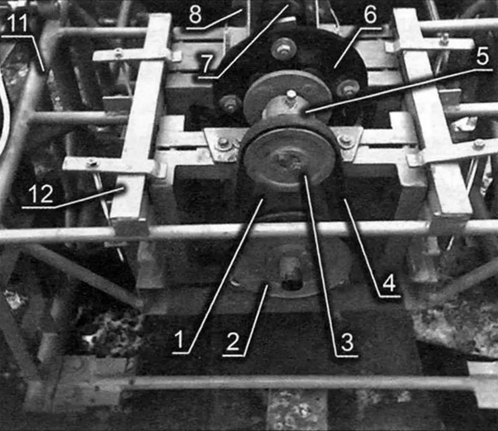
1 – slewing gearbox; 2 – suspended cradle; 3 – bracket of support roller; 4 – support roller housing; 5 – plate for attaching bearing housing to frame; 6 – housing with bearing; 7 – latch; 8 – cradle slewing shaft; 9 – handwheel for slewing cradle with mixer
Using a driven shaft with a pulley instead of a rigid direct connection of the “barrel” to the gearmotor is necessary to provide a gentle operating mode for the electric motor and gearbox. If the drum is overloaded by weight, the drive belt can slip, thereby reducing the load on the motor and gearbox.
The main platform gives the other plates some freedom in mounting, which makes it possible to align the hubs coaxially with the axis of the drum regardless of fabrication tolerances and wear of the rubber belts. In addition, belt tension can be adjusted by shifting the gearmotor.
In the lower part of the cradle there are eight ball bearings on which the “barrel” rolls. Their mounting follows a “floating” scheme that compensates for inaccuracies in fabrication of the assemblies. Two bearings are mounted on a single shaft that passes freely through the hole of the mounting bracket.
In the upper part of the cradle there are support bearings—two on each side of the drum. The bearings are installed in housings that allow adjustment of their contact with the drum raceways.
Two hubs are used in the design. One is made from the front hub of an Oka car, the other is homemade.
The two are flexibly connected by a rubber damping washer cut from 16 mm thick conveyor belt.
One of the shafts used is also a half‑shaft from an Oka car.
The use of an automotive hub is due to the presence of a double‑row bearing in it. Another advantage of such a hub is the pivoting joint mechanism, which compensates for errors in fabrication and alignment of both installed hubs. Hubs and half‑shafts from any front‑wheel‑drive car can be used.
The Oka hub is flexibly connected to the drum by a rubber damping washer, also made from 16 mm conveyor belt. The use of damping rubber washers ensures soft starting and smooth operation of the mixer.
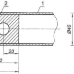
The second hub consists of a housing with two ball bearings and a shaft, one end of which is connected to the other hub through a rubber washer; a pulley for the drive belt is mounted on the other end. The pulley is taken from the air compressor of a MAZ truck.
Since the drum “rolls” on bearings in the cradle, is not rigidly connected to the hub, and does not “hang” on it, there is practically no vertical axial load on the hub bearing, which ensures its long service life.
The electric drive is a gearmotor with the following characteristics: 600 W, 380 V, 20 rpm at the output shaft.
The ball bearings in the gearbox have been replaced with double‑row roller bearings.
Because the drive was intended for use only on a single‑phase AC mains, the stator windings of the electric motor and their connection scheme were modified. The windings are made from enamelled wire, additionally tightly wound, turn to turn, with 0.1 mm fiberglass thread. This provides extremely reliable high‑voltage and heat‑resistant insulation, eliminating the possibility of turn‑to‑turn short circuits in the windings and failure of the motor. Even if the enamel on the wire is scorched, turn‑to‑turn shorting is impossible. After the windings were placed in the stator slots, they were not impregnated, which improved heat dissipation.
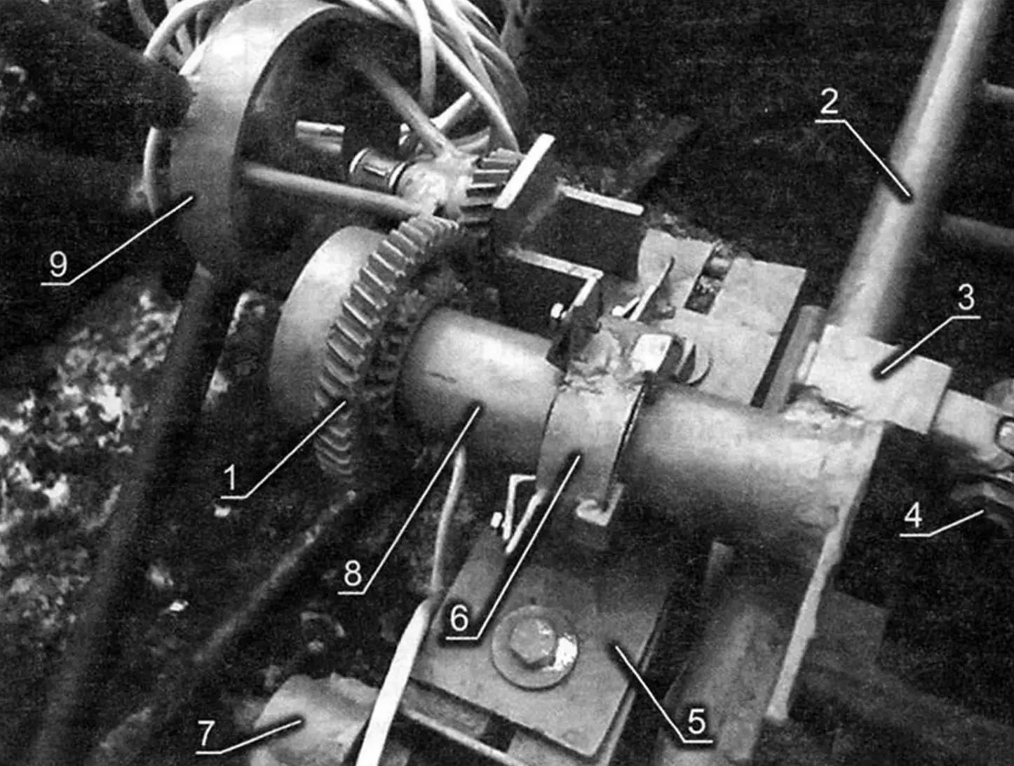
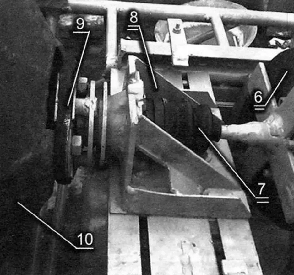
1 – gearmotor; 2 – driving pulley; 3 – driven pulley; 4 – V‑belt; 5 – hub of first shaft stage; 6 – rubber damping washer; 7 – second shaft stage (half‑shaft from Oka car); 8 – bracket for secondary shaft with welded Oka hub; 9 – rubber damping washer; 10 – drum; 11 – drive subframe; 12 – cradle
The winding connection scheme was changed. One of the three windings was connected in parallel with the other two, which provided additional EMF and eliminated the counter‑EMF that slows the operation of a three‑phase motor on a single‑phase mains and leads to power loss.
This connection scheme made it possible to obtain motor power in the range of 400–420 W, which is much higher than when a three‑phase motor is connected to a single‑phase mains using the traditional scheme.
The motor is started by a starter button taken from an old washing machine. Reversal of the motor is achieved by switching the windings with a cam‑type rotary switch rated for the appropriate current.
The wiring is made with stranded cable. The conductors are laid in a flexible “armor hose” wrapped in two layers of insulating tape, providing relative tightness. For easier installation, wires of different colors are used.
The frame of the concrete mixer is demountable, consisting of two side posts and three connecting ties. One of the posts carries a platform made of 25×25 mm angle for mounting the capacitor banks, as well as the housings of the start button and reverse switch, which are made of 0.8 mm galvanized steel.
The covers of this housing are designed so that they do not allow the motor reverse to be switched while the motor is running.
The capacitor bank housing is made sealed. Its bottom is made of 15 mm textolite, and the side walls and cover are made of 0.8 mm galvanized steel. The cover and side walls are joined with aluminum rivets. On the same side post there is a latch of the “rifle bolt” type, which securely locks the cradle and, accordingly, the drum in three positions: mixing, horizontal (for convenient cleaning and washing after work), and discharge.
The side posts of the frame are made from one‑inch gas‑pipeline pipe, and stiffness is provided by braces made from half‑inch pipe.
The side posts and ties (two horizontal and one vertical) are bolted together.
Additional support half‑posts are welded to the lower front parts of the side posts, and the wheel axles are located at the center of gravity.
The mixer wheels are solid rubber. It is advisable to have two wheels on each axle to reduce specific pressure on the ground.
A slewing mechanism and a tilting crosshead are mounted on the vertical post, allowing the cradle to be moved from the working position to the discharge position.
To avoid electric shock, the concrete mixer is grounded. The ground conductor runs separately from the motor and is bolted to a side post of the frame, then connected to a metal pointed rod 12 mm in diameter and 500 mm long. Before work begins, the rod is driven into the ground.
The concrete mixer is collapsible. It takes only 30–40 minutes to put it into “transport” condition; about the same time is required for assembly after transport. In disassembled form it can easily be placed even in a VAZ‑2104 car.
After it was built, my concrete mixer worked continuously throughout last autumn “from morning till night”: it processed more than a KAMAZ truckload of sand and six such truckloads of crushed stone, and the amount of water used was beyond counting!
Now the mixer is operating flawlessly in one of our gardening cooperatives.
“Modelist‑Konstruktor” No. 11’2013, A. KUKUSHKIN
Recommend to read
 SIMPLEST ANTI-THEFT DEVICE
What devices are invented so that the attackers couldn't steal a car. Steering lock, gear shift knob, wheels, dodgy electrics off, the impact on the psyche of a siren, light shows and... ULYANOVSK SUVS
The cars of family UAZ-450 UAZ-452. General offensive on Moscow was deployed by the German command at the end of September 1941. As of October 10, the State Defense Committee adopted a...
