We have long been accustomed to the prefix “electro” in modern musical terminology. Appeared such names as electric guitar, electro, and even the ensemble of electronic musical instruments. Many of the tools have become more rich shades of sound, when a duet with them stands electronics. Bypassing it is only people’s tools. Plays a role, apparently, the fear to violate the purity of the already established sounds. But this is not so. Even such a simple instrument like a balalaika, will be able to gain more power, become a true soloist of the orchestra of folk instruments, if you supply the pickups. Today’s publication is devoted to one of the variants of the “electrification” of the balalaika.
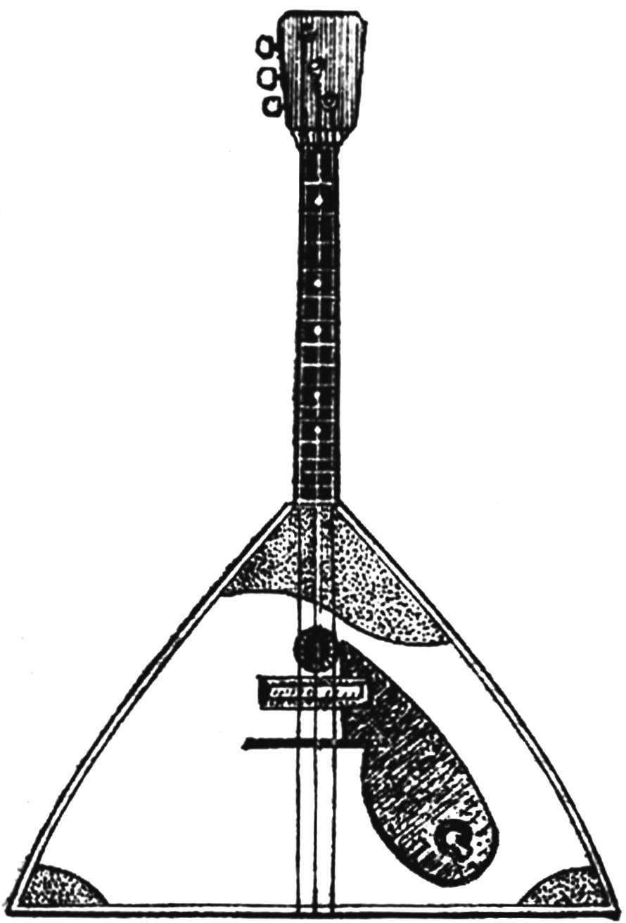
The tool, which will be made on the basis of conventional balalaika length scale (distance from nut to top of stand) 438 mm (± 5 mm) and a total height of stand 13 mm (Fig. 1).
An important part of electrobalance — the pickup (Fig. 2). The quality of fabrication depends largely on the tool. The core of the adapter is made up of several permanent magnets electric motors for toys. The magnets will be turned on a sanding disc. They can be made from a file or a magnetic ring ion trap tubes previous releases.
File release handle on the abrasive wheel to the desired size, hardened, and finally magnetized. In the second case the ring through the cardboard sheets are crushed in the vise, and the shards to grind abrasive circle. Break the ring with a hammer do not: reduced magnetization of the metal.

 We have long been accustomed to the prefix “electro” in modern musical terminology. Appeared such names as electric guitar, electro, and even the ensemble of electronic musical instruments. Many of the tools have become more rich shades of sound, when a duet with them stands electronics. Bypassing it is only people’s tools. Plays a role, apparently, the fear to violate the purity of the already established sounds. But this is not so. Even such a simple instrument like a balalaika, will be able to gain more power, become a true soloist of the orchestra of folk instruments, if you supply the pickups. Today’s publication is devoted to one of the variants of the “electrification” of the balalaika.