In boiler design applied water ten pretty big power — 3 kW. The current consumed by the heater is about 15 A. Therefore, the switching device shall withstand a load of at least 15 and to be fast. Phase must be supplied to the switching element, and “O” to connect constantly. This design incorporates two of the microswitch 16 A and 380 V (schematic diagram of the boiler shown in Fig. 2.)
DETAILS AND DESIGN
For the manufacture of water heater you need:
1. Water heating element (ten 3-220).
2. Wire diameter 3 mm and length of 10 m
3. Rubber hose inner diameter of 22 mm and a length of 1300 mm.
4. Rubber tube inner diameter 8 mm and length 1000 mm.
5. The two unions.
6. Two washers diameter 12×20 mm.
7. Two nuts M 12×1,25.
8. Two collars made of tin thickness of 0.5 mm.
9. The pressure sensor Assembly.
Preparation of parts for Assembly is as follows. Water heating element, you must flatten the angle of 50 — 60°. Grind, file the flanges and the threads on the heads (Fig. 3). Tightly wrap the wire of the heating part of the heating element over the entire length in increments of 10 mm. Now for the heater winding will push the hose on which, departing from the edge approximately 50 mm, it is necessary to make a hole under the fitting. Inserting the last retaining nut by placing it under a washer. Followed by the free end of the hose to pull the wrapped wire heater (for ease of the wire can be lubricated with grease) and to level the edges of the washer nozzle with the edge of the milled head of PETN. At the opposite end of the hose to outline the hole for the second fitting. Pulled off the hose to make a hole, insert the fitting and fasten with nut and washer. Install the hose in place, trim the ends at the edges of the heating element and firmly tighten clamps. Cranking the heater to its original position. (Fig. 3 shows one end mounted heater.)
Base, cover, bracket rocker arm, the rocker arm and clamps are made of galvanized sheet with thickness of 0.5 mm. All parts are mounted on the base. Cut them out strictly according to size, then drill holes and bend at the bend lines.
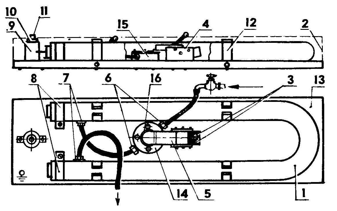
Fig. 1. The design of the boiler:
1 — heater, 2 — cover (conventionally not shown), 3 — switches, 4 — arm rocker, rocker 5, 6 crimp sleeve and the tubing pressure sensor, 7 — fittings, 8 — collars, 9 — stoick cartridge 10 — cartridge 11 — indicator light bulb TN-0,2, 12 — clamp, 13 — base, 14 — ring-washer. 15 — the case of the pressure sensor, 16 is a rubber diaphragm.
Fig. 2. The schematic circuit diagram.
Fig. 3. Installation of the heater.
The housing of the pressure sensor made of brass. Ring-washer can be made of steel, with the inner part must be rounded (remove chamfer). Crimping sleeve and tube will fit the car. It is important that the inner diameter of the tubes was not less than 4 mm. the Diaphragm can be cut from a car camera.
Electrical power it is advisable to make a separate cable with a diameter of not less than 3 mm2. After installation, you must insulate all exposed conductive parts.
You can now begin to assemble the boiler (see Fig.1). Adjustment it is mainly to check microswitches: do not connect heater to the network feed from the faucet through a hose to the pressure sensor and turning the yoke, try to achieve simultaneous actuation of both switches. After adjustment secure the boiler on the wall, cut holes in the lid for the input and output hoses hot and cold water. Grounding the casing of the boiler, make sure it is working.
If you can not buy a powerful microswitches, use of small low-power, which will actuate the magnetic contactor that feed the heater with a trigger coil on 220 V. In this case, however, will slightly change the mechanism of on-off heating element and its electrical schematic.
Remember that when you stop, the heating element cools immediately, so it is not recommended to abruptly turn off the water and wait for 30 seconds when de-energized the heating element, until it will not go cool water. This can be achieved again by adjusting the rocker arms. At low pressure the diaphragm does not touch the rocker arm (between them there should be a gap of 3 — 5 mm).
Adjusting the faucet flow water inlet of the boiler, you will achieve its desired temperature at the outlet. The amount of heated water will vary from 1 to 1.5 l/min.
V. KARAVACHEV,
p. Bohr, Kustanai region.
Recommend to read RENAULT SANDERO Moscow plant AVTOFRAMOS commenced Assembly of RENAULT SANDERO, Renault created the firm on the basis of the popular sedan RENAULT LOGAN. A new car is a compact five-door five-seater... GENUINE RUSSIAN NAVY The victory over France in the war of 1870 opened to the Federation of German States, formed under the auspices of Prussia, a completely new Outlook In Central Europe is variegated... 
 The proposed boiler is designed for heating cold water (temperature up to 60° C) in apartments with Central or local water supply. Facilities associated with the operation of the boiler, no doubt, be appreciated by every hostess.