In the textbook “machine Parts” (ed.Reshetova. M.: Mashinostroenie, 1974) find the main parameters of the drive roller chains and calculation formulas. Use them and take several designations that will be required in the future:
t — step sprocket (chain),
z — the number of teeth
dd is the pitch diameter,
di is the diameter of the circle of hollows,
de is the diameter of the circle of projections,
d1 is the roller diameter of the chain.
Now, define the pitch diameter by the following formula:
Carved On a lathe from a steel sheet billet sprocket 12 mm thick (the distance between the connection plates of the inner links of the chain with a pitch of 19,05 mm gauge — 12.7 mm) and a diameter equal to the sum of diameters of dividing the circumference of the roller chain (assortment — of 11.91 mm) and an allowance of 20 mm (for the stability on the supporting surface when drilling). We get:
Hone of the bore hole in the workpiece with a diameter of dn = 25 mm. similarly make one more workpiece — trial, with the same planting hole (the accuracy of the other sizes are optional).
Bring the selected gear thickness up to 12 mm (thermally pre-release it), optochip on both sides on a lathe. For coaxial gear arrangement and procurement of sprockets in the conductor will blow a stepped bushing with a Central hole for clamping bolt M10.
The step height 1 mm smaller than the thickness of the gear and preparations, and their bores bushing go in without backlash. Carved also two washers with a thickness of 4 mm under pinch bolt M10 — one under the head and the other under the nut.
In steel strap with a thickness of 10 and a width of 25 mm drill the drill hole with a diameter of 0,1…0,2 mm smaller than the roller diameter of the chain (in our case, 11.8 mm). This end of the strap conductor temper. At the other end make a slit with a width of 8.2 mm (length depends on size made of asterisks). In gear at a slight distance from the circumference of the depressions drill two holes for the adjusting bolts M8 to install on their target-the conductor does not touch the pinch bolt washer.
Fig.1. Conductor Assembly:
1 — strip conductor, 2 — adjusting bolt, 3 — pinch bolt, 4 — washers, 5 — sleeve, 6 — gear, 7 — fixing pin, 8 — billet sprocket; a — drill hole.
Fig. 2. Auxiliary marking devices:
1 — insert 2 — the template of the tooth profile, 3 — limiter, 4 — pattern of transverse tooth profile.
Connect billet sprocket and gear coupling bolt through the bushing. On the first core outline i center and drill a hole for a retaining pin, which in- ‘ burghers in the cavity between the gear teeth. The height of the protruding part should not exceed the thickness of the latter. For further markup will also produce liner with a spike — hole of the saw blade (Fig.2).
Subsequent technology is as follows:insert into the bearing hole of the test workpiece insert the spike down. Compass outline center of liner (intersection arcs) and the radius calculated by the formula:
outline for a trial harvesting of the circumference of the depressions. Adding to the calculated radius value d1 will conduct another circle.
Collect the test conductor with the workpiece (Fig. 1). Align bushing hole with the resulting circles so that they were tangent to the projection hole, tighten the nuts of the adjusting bolts.
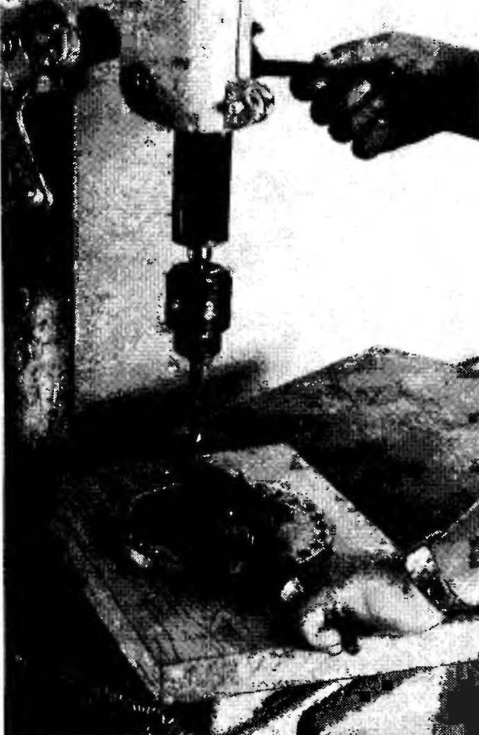
Introduce the drill bit with a diameter of 11,8 mm drill hole until it comes into contact with the workpiece and pressing the feed lever, start the machine, enabling the conductor to “clarify” his position. Then, gradually realizing the feed, will do a test drilling.
Caliper to check the diameter of the workpiece the length of a line between the edges of the planting holes and trial. It should be equal to:
Adjust the position of the strap conductor and will achieve a more accurate determination of the drill between the outlined circles. Finally tighten the nuts of the adjusting bolts.
Trial billet to replace the bulk and as described above, the locking gear through each tooth, drill all 27 holes. (To avoid biases must be taken that no dirt, nicks, burrs and the like at the point of contact of gear teeth with the locking pin.) Get the base of the teeth and valleys of stars, which does not require further processing.
Then undercut the workpiece on a lathe to the diameter of the circle of projections defined by the formula simplified calculation:
From a piece of saw blade cut a template of the profile of the head of the tooth. Placing it between the holes of the billet sprocket, insert the thorn of the liner and draw the profile of all teeth with a needle. We do the same on the other side of the workpiece. Connect the line ends of the opposite lines.
Cut the metal with a hacksaw the excess metal between the heads of the teeth with an allowance of 1 mm, using control limiter (see Fig. 2) made of strips of sheet metal with a width of 12 mm (the thickness of the sprocket). Finally, we will bring the profile of the teeth on a manual or electric sharpening fine sand around.
A template of thin paper, pasted on one of the teeth, denote the tooth profile in the transverse direction and epilim billet sprocket with a flat file, attach it to the axis of the winepress.
When selecting the gears should consider that the accuracy of manufacturing is higher in those cases where the dimensions of the workpiece and its close.
Observing the described technology and skillfully wielding tools, you can get a homemade sprocket, differing little in appearance and quality from the factory. These I use in the transmission of the tillers, which has served me flawlessly for several years.
I. GUBANISCHEV
Recommend to read THE THREE-STEP CUTTER… Like to gain the space velocity of the rocket help a three stage engine, three cutter proposed Odessa innovator P. I. Podolyan instead of one, possible to achieve "cosmic" speed cutting... CABLE KNIFE? Compact and handy knife for "cutting" the cable created by the participants NTTM from Leningrad. Tool — it was called Baltika is designed for longitudinal and cross cutting of hose... Scroll back to top
 Amateur Designers often used in the transmissions of their cars, the chain transmission. And sometimes faced here what problem: for the calculated gear ratio chain couples find it difficult to choose ready-made sprocket with the desired number of teeth. But them it is possible to make yourself using the jig, assembled on the basis of the gear closest to the desired amount. Suppose you need a sprocket with 26 teeth and pitch of 19,05 mm. will Select the gear with the same or similar number of teeth. For example, 27. (In this case, the gear ratio will change slightly by 4%.) The gear is hardened, has a thickness of 19 mm and a bore diameter of 20 mm.