In addition microcircuits K561LA7, led АЛ307Б and КТ3102Б transistors (VT1, VT2) and КТ3107Д (VT3) in the Assembly of signaling devices used resistors MLT-0,125, capacitors KLS (01, C2, C4) and C50-6 (Sz, C5), piezo buzzer SP-1 and toggle switch MT3 and microswitch MP 12. As T1 after a small upgrade fitted matching transformer from the portable radio receiver “VEGA-402”, “Selga-404” or the like. This per-mallowy the magnetic core cross-section 6×5 mm with windings. The modernization consisted in the following. Unused L2 it removed. Primary 1600-turn coil is reduced to 650 turns and is used as L2. But 1.1 is wound again (70 turns of wire PEV-2 0,15).
Power supply alarm are two series-connected battery 3LR12 from a pocket lantern.
Strength mechanical mounting and reliability of the electrical connections of the components enables the circuit Board from a one-sided foil 1.5 mm thick plastic. Its simple topology, designed to perform any known methods, are unlikely to cause problems for any of hams.
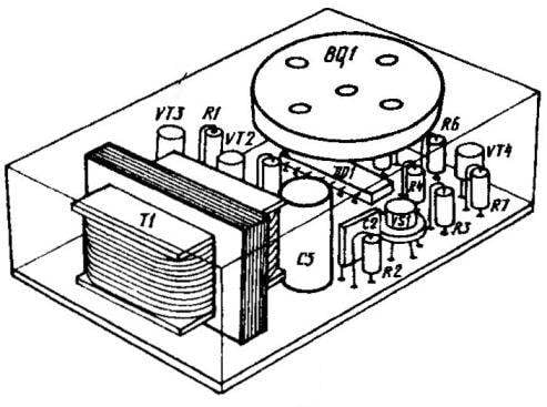
Layout option a homemade alarm
The adjustment of the device is simple too. In fact, it is reduced only to obtaining the greatest volume of sound alarm Yes achieve clear circuit operation at the time of the release of SCR. The first is achieved by selecting the value of capacitor C4, in which the pulse repetition frequency of the generator coincides with the resonance piezoelectric crystal of the alarm occurring at about 3500 Hz. Well, the second is finding the optimal ratio of the resistors in the divider R4R5 for supplying the respective voltage at inputs 1 and 2 are logical cells DD1.1.
Assembled electronic part of the device, including a power source, a hidden, inaccessible location (e.g. under the ceiling on the mezzanine). As securely hidden from prying eyes switch SB1 should easily accrue to the owner. The wiring between the parts of the device is hidden, eliminating any hint about the location of the alarm.
Depending on the location of the device layout of the alarm device can be performed in different ways. In most cases, acceptable version of the assemblies in the General case as a circuit Board and a power source and alarm.
Replacement battery cell or battery bolsaescola network adapter here is hardly advisable: prudent attacker will certainly try to shut off the power of the planned flats with flap on the landing. In favor of Autonomous power sources and the fact that consumption alarm current minimum. Then, the battery cell or rechargeable batteries will last a long time.
Yu PROKOPTSOV
Recommend to read
 PZL TS-11 Iskra (Poland)
The plane was developed at the request of the Polish air force jet training plane. It was the first jet car built in Poland. Work began in 1957, the First prototype with a British... CUT FRUITS AND ROOTS
A rural resident with a large garden and cattle, will love shredder, made by a craftsman from the village of Bornukovo Nizhny Novgorod region Yevgeny Kulikov. With its help in the...