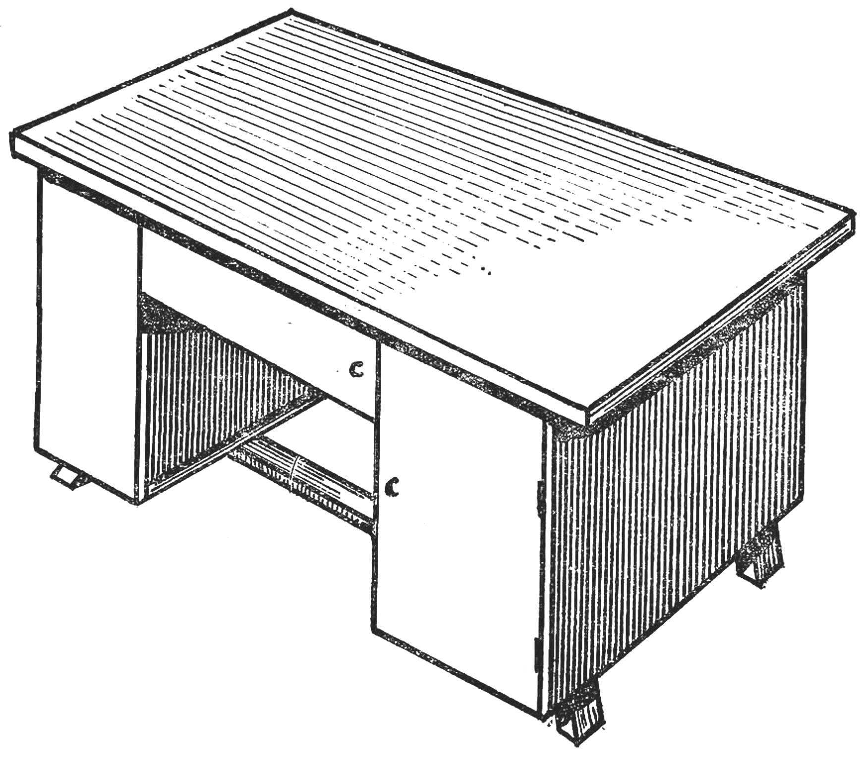
 Where to store the tools, how best to equip the workplace? To these questions every fan of tinkering responds differently. Want to share the experience easy and compact work area. odnorodnogo Desk, modified and reworked (Fig. 1).
First of all, it is removed from the top cover. Between the table and the left wall of the table attached to the working Board, is lowered relative to the top of the table of 150-180 mm. Top Board cover for table is hinged, so it’s lifting. The rest of the equipment is as shown on the drawings.
On the preparation table to the operation and subsequent cleaning of the instruments takes the least time. With proper organization tool storage: each subject is a place.
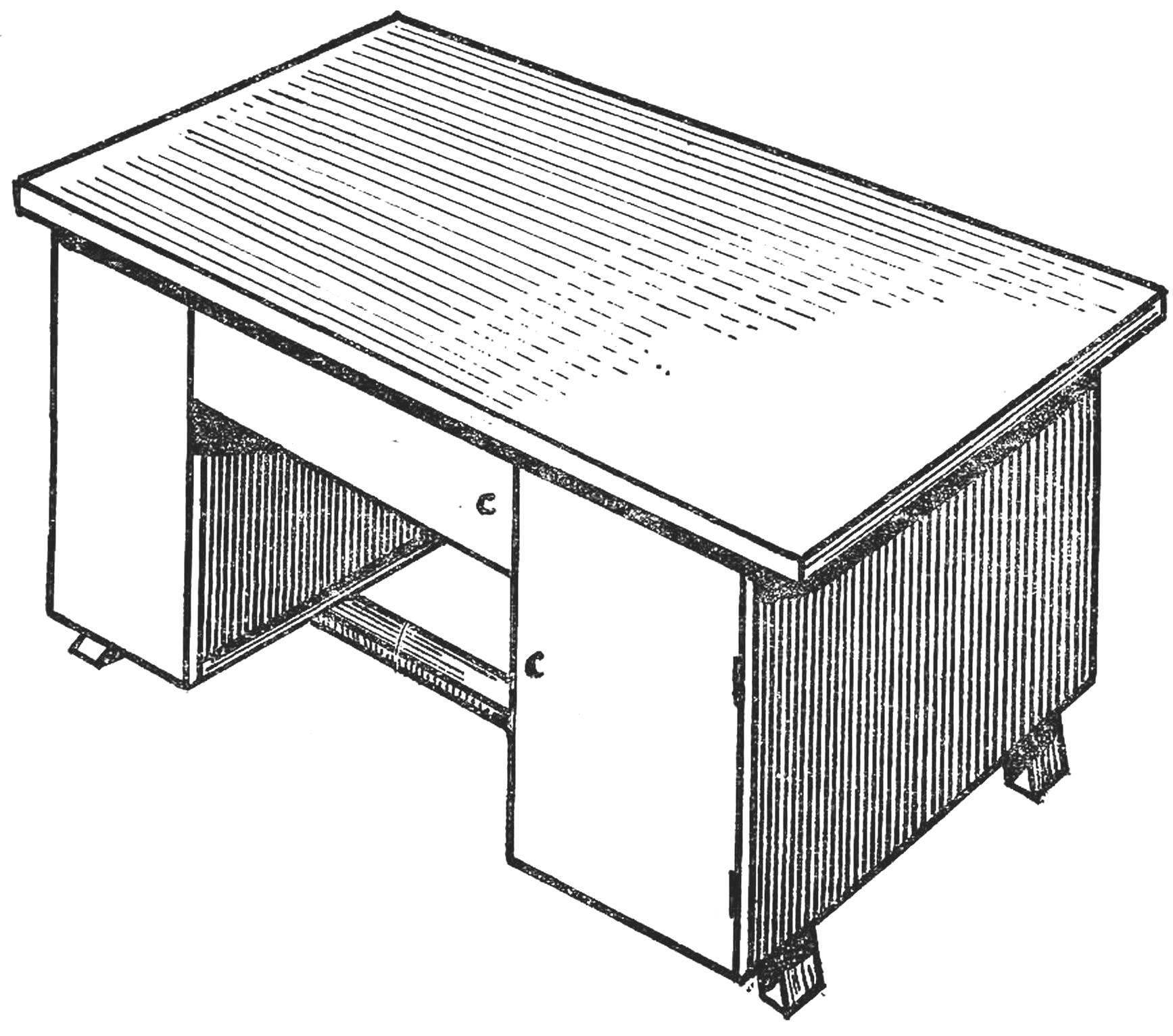
Tools permanent use are placed on the bottom cover in the zone 11 (Fig. 2), the rest are stored in the drawers. Knife, pliers, tweezers, awl, needle files, screw drivers are mounted using the brackets from thin sheet metal or of the hinges leather strips.
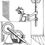
The rear upper corner of the tables (Fig. 3) used to install single-phase motor (Fig. 4).

Fig. 1. The appearance of the closed table-workshop.
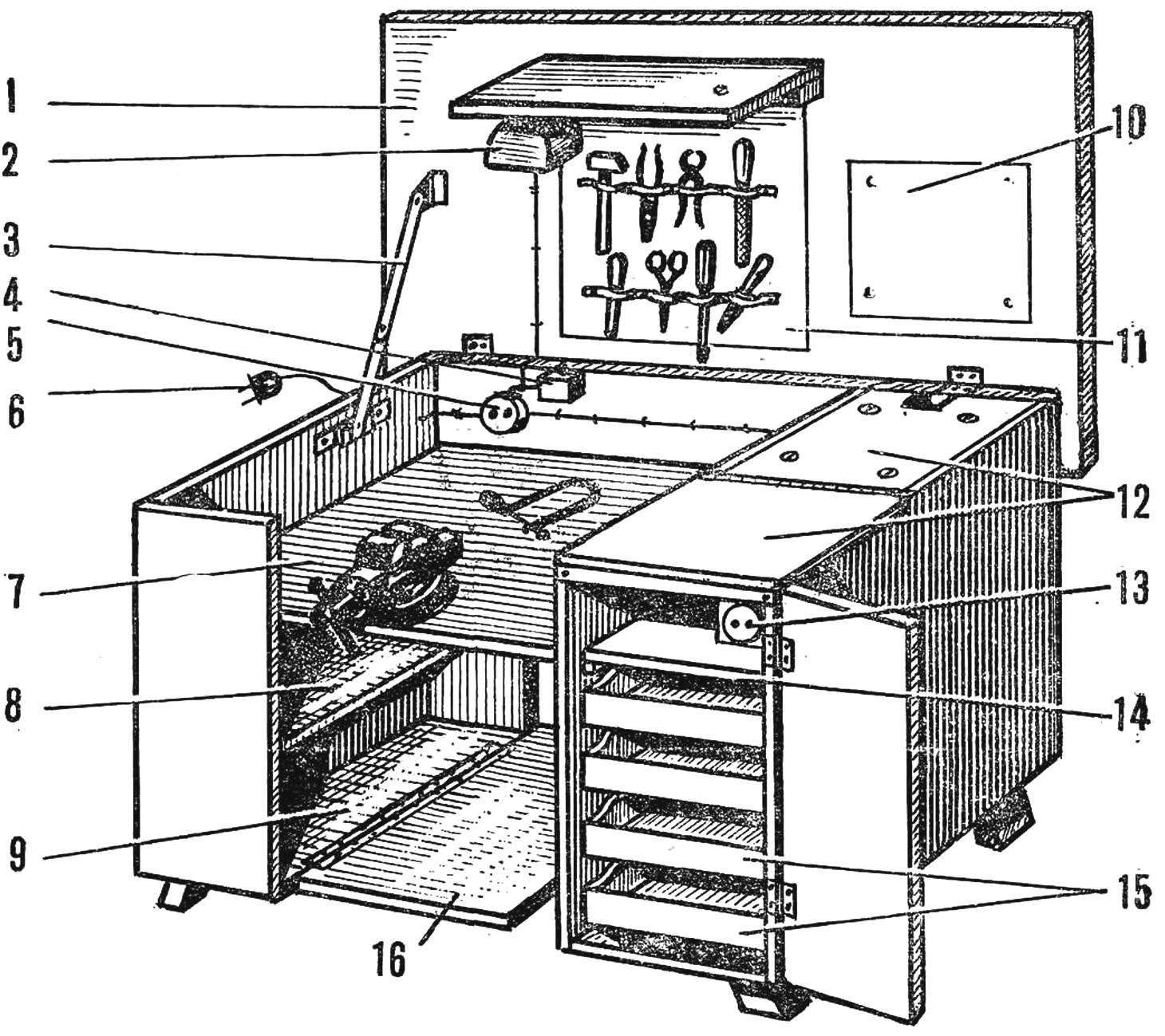
Fig. 2. Table-workshop in working position:
1 shelf lamp, 2 — lamp, 3 — fold focus, 4 — MIZA microswitch (2 a, 220 V), 5 — left plug, 6 — plug, 7 — working plane of the table 8 — shelf side, 9 — a place to store materials and rarely used tool, 10 — mounting location drawing or schema, 11 — zone of fastening of the basic tools, 12 — front and back halves of the cover tables, 13 — right plug, 14 — plywood sliding shelf, 15 — boxes, 16 — flip cover.
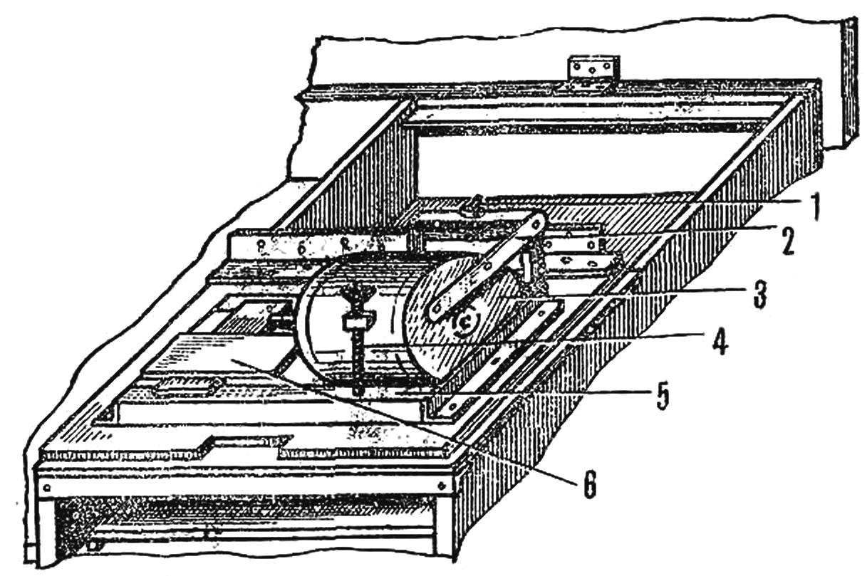
Fig. 3. The form of tables with a folding rear half of the cover:
1 — switch motor 2 — mounting bracket motor, 3 — motor, 4 — screw height adjustment of the motor shaft, 5 — frame, 6 — caliper.
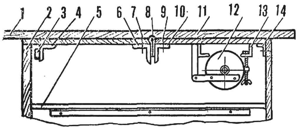
Fig. 4. Slit closed bedside table (right side view):
1 — tabletop, 2 — door cabinets, 3 — plug, 4 — front half cover tables, 5 — plywood sliding shelf, 6, 10 — dural corners 40X40MM, 7, 9 — rivets or screws M3, 8 — piano loop 11 — back half of lid tables, 12 — motor, 13 — frame 14 — of the supporting dural area 40X40MM
The motor shaft end protochen own bearings under the Morse taper. Using a variety of tools-nozzles, you can use an engine for grinding, drilling, lathes, polishing and other works. The method of mounting the emery stone and puller to it is shown in figure 6. In the bottom of a Chuck hole drilled and tapped M6 for the puller.
On top of the table is arranged additional lighting. Homemade lamp mounted on the front Board: it is automatically activated by a microswitch located on the back of the table and trigger when the table cover is raised.
The voltage from the housing outlet is supplied via the flexible wire through a lateral wall of the cover. The table has two plugs. The left is for connecting the transformer or the measuring device, the right is primarily used for soldering, then the cord does not interfere. This also connects to and the motor.
All the extra wood of the table is made from veneered chipboard (or plywood the same thickness, or well proestrogenic boards).
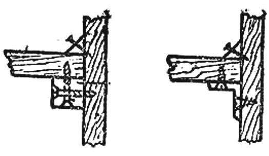
Fig. 5. The options for fixing a working plane of a table.
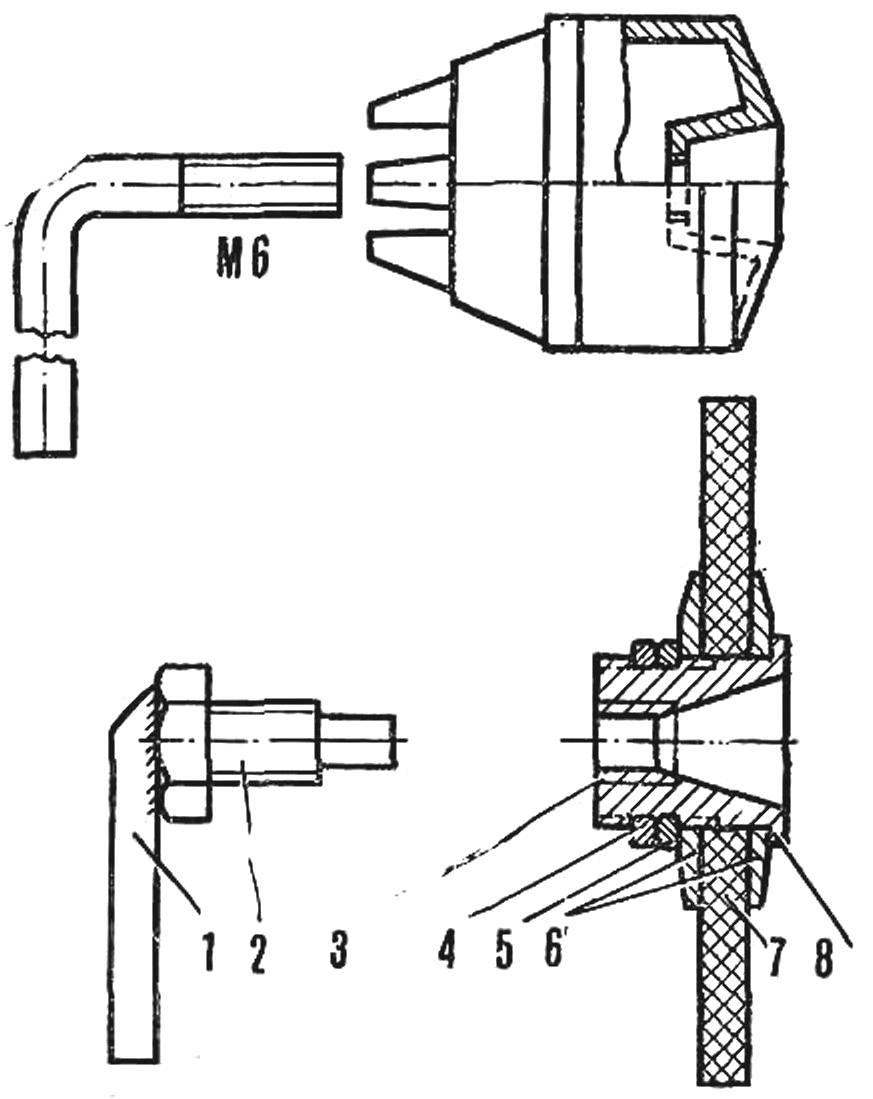
Fig. 6. Clamping drill Chuck, the stripper, the sandpaper:
1 — the handle of the puller, 2 — head puller (bolt M10), 3 — bushing, 4 — lock nut 5 — nut; 6 — washer, 7 — emery wheel, 8 — Morse taper.
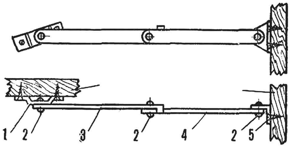
Fig. 7. Folding the-blank cover Assembly:
1 — clip 2 — rivets 3 — plate ledge, 4 — plate 5 — area.
The most simple means of securing the work plane table shown in figure 5. The top cover is hinged and held in a vertical position, a retractable stop (Fig. 7). Both parts its made of duralumin area.
Half cover stands are made from three layers of plywood. The front is fastened with rivets to the piano hinge (Fig. 4). The rear half — shelf rolling area M3 screws with countersunk heads. The second shelf area — M3 screws to a conventional piano hinge. Fixed dural area embedded in the side wall cabinets not less than three quarters of their thickness and attached with screws. Area 14 (see Fig. 4) is a structural stiffener. It is embedded flush with the ends of the side walls of the cabinets and attached to them with screws.
For a similar construction can be used dvuhtumbovyh table.
V. SLAVES, Arkhangelsk
Recommend to read
 DUO ROLLERS
Original brush two foam rollers used for painting walls and ceilings V. Vakulenko from St. Petersburg. They are located on the shaft so that rotates in contact with each other, the lower...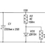 THE SUPERCAPACITOR IN YOUR POCKET
We offer a simple pocket radio with low voltage power from the supercapacitor. The receiver is fully on transistors, because the low voltage does not allow to use the existing chips...
