Main requirement: achieving the two degrees of freedom of a telescope (rotation around horizontal and vertical axes), easy (4-5 kg) and compact size.
The resulting design is shown in Fig.1. Mullion with fixed therein the tube of the telescope rod is pivotally installed in the support thrust bearing plugs, providing a 90° rotation (from horizontal to vertical position of the pipe). The plug rests on the base and can be rotated freely by 360° around the vertical axis. Due to these two movements is pointing the telescope at almost any object in the sky at the place of observation.
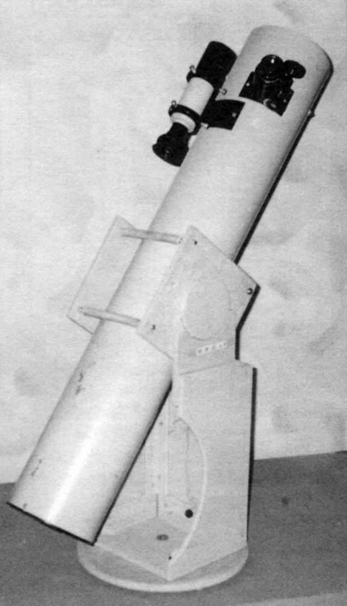
Fig. 1. The telescope of the dobsonian mount:
1 – medium; 2 – telescope; 3 – plug; 4 – the vertical axis (screw 5h30); 5 – strip (Whatman, 2 – 3 pieces); 6 – base (plywood s12 – 14); 7 – bearing (rubber, 4 pieces)
Fig. 2. The centerpiece:
1 – axis (plywood s10,2); 2 – coupling (stud M6, L175, 3). 3 – side panel (plywood s10, 2pcs.); 4 – safety tube (rubber hose, L110,4 pieces); 5 – nut M6 (16 items); 6 – screw 3×20 (10 PCs); 7 – shortened coupling (stud M6, L158); 8 – trim (leather, rubber, s2 – 2,5)
Fig. 3. Fork:
1 – bottom; 2 – side wall (2); 3 – bearing thrust bearing (2 PCs); 4 – back wall; 5 – a cushion (foam, packing foam, etc); 6 – plinth (duralumin area 15×15); material of parts 1 – 4 – plywood s10
Fig. 4. Circular gregoratos:
1 – workpiece; 2 – axle (dowel Ø5); 3 – cutter (plug); 4 – the lever (a bar of 30×30)
Fig. 5. Build the side walls of the plug bearing:
1 – conductor base (plywood s12 — 14); 2 — retainer (steel rod 05); 3 – bearing; 4 – a lining (plywood s10); 5 – side wall
Fabrication of the mount starting with the centerpiece. Of 10 mm plywood cut two sides (squares 175×175 mm) and two half-axles with a diameter of 96 mm. For cutting of cylindrical parts using a simple device – a circular gregoratos. In a wooden block, cross section approx 30×30 mm drill two holes with a diameter of 3 – 3.5 mm center-to-center distance equal to the radius of the future drive. In extreme hole hammered raw metal dowel with a diameter of 5 mm the axis of the cutter, and in another hole, closer to the middle of the bar, the other dowel end of which is sharpened like a chisel. The dowels should protrude from the bar at 8 – 10 mm In the workpiece according to the center for the future of disk drill through hole with a diameter of 1.5 -2 mm. In it install taper dowels-axis and hold it in this position using the bar as a lever in a circular motion cut through the plywood half the thickness. Next, take out the gregoratos, turn the workpiece and repeat the previous operation to complete cutting of the disk. It only remains to smooth the ends with emery cloth.
In the manufacture of a mediator the main task is to ensure the alignment of the axles. The following Assembly technique:
1. At the intersection of the diagonals mark the center of the side walls and drill holes with a diameter of 3 mm.
2. The holes in the rod reams also to 3 mm.
3. Glue the axle shaft to the sidewall, compressing them installed on the center bolt M3.
4. After the glue dries connect the sidewalls on the axis of a long M3 bolt, align the edges, and mark holes for zip ties, stand center-to-center distance of 150 mm.
5. By marking the drill 4 through 6-mm holes.
6. One pair of reams holes to a diameter of 14 mm to a depth of 5 mm (the cropped tie).
Then, after taking the technological bolt M3, strengthen glued axle screws and the sidewall on the inner side pasted strips of skin thickness 2 – 2.5 mm (you can use an old leather belt). In conclusion, mating sidewall tie – pins MB. Three studs with a length of 175 mm and one shortened (158 – 160 mm) is installed in the lower left corner that when turning pipe in a vertical position, the mullion does not touch the inner wall of the plug. For protection of a telescope on the studs are tightened the segments of rubber tubing. The distance between the sidewalls of the pre-aged is equal to the diameter of the pipe plus the clearance of 1-2 mm.
Installing pipe into the mullion, it is necessary to make balancing the entire Assembly to provide smooth rotation and stable position of the telescope after pointing at the object of observation. To do this, under the semi-axis of the centerpiece summing two parallel bars with height of 100 – 120 mm and can hold the pipe by hand, look, whether it stays in the position of indifferent equilibrium or one of its ends pulls. If the balance is disturbed, move the tube along its axis until then, until the stable equilibrium. Then using the tie wraps carefully fix the pipe in the center.
Design and production of plugs starting with the calculation of its main parameters: the height and the distance between the side walls.
Fork height should be such that in the vertical position of the pipe between its lower end and the bottom plugs were guaranteed a gap of approximately 25 mm.
Fork width is the sum of the width of the centerpiece without the rod (140 mm) clearance between the outer planes and inner planes of the thrust bearing (0.5 mm per side) and the thickness of the side walls and the thrust bearing (40 mm). The dimensions of the rear wall and the bottom of the fork is derived from its height and width (see drawing).
Fabrication of the side walls and glides are recommended in packs, in pairs, so they turned out exactly the same: it will automatically provide aligned bearing surfaces.
The fork Assembly should be conducted in the following sequence:
1. Side walls bonded with the supporting thrust. The operation produced in a special jig, consisting of a base (a scrap plywood sheet) and five pins. During layout and installation necessary to sustain the size of 440 mm and perpendicular to the x and y axes. The position of the thrust bearing in the conductor is determined by the pins e, f, K. the Side wall are laid on a greased glue the thrust bearing and spacer from 10 mm of plywood, locking its position by pins, CI, E. by gluing opposite pairs of wall parts have at the bottom under support.
2. After drying, the adhesive joints of parts strengthen the four screws 3×20.
3. Glue assembled the side walls to the rear.
4. The obtained U-shaped design stick to the bottom.
5. The joint of walls with the bottom strengthen small wooden plinths or duralumin corners 15×15 or 20×20 mm.
6. On the back glue on a square of foam or foam pillow – emphasis for of a telescope during transport.
Next plywood thickness 12 to 14 mm cut out (for the above technologies) base – disk with a diameter of 280 mm. On the lower surface of the disk fasten screws four pillars – thick rubber gaskets from the faucet.
Before final Assembly mount all necroshine the surface of the plywood parts paint and oil paint.
The plug is attached to the base with wood screw 5×30; protruding from the bottom of the screw part sawn off. Between the bottom and the base to reduce friction and improve the smoothness of rotation of the fork around the vertical axis set gaskets – two circles of paper, oiled soap. If necessary, the friction force in the contact can be adjusted by the diameter of circles (I – 140 mm), using paper instead of other materials (e.g., linoleum), the amount of lubricant (soap) or change the contact force by means of a screw – axis.
Experimentally I found that the optimum friction torque should be 0.8 – 1 kg, see in Other words, if you move a weight of 25 g along the pipe from center to the tip, the correct adjustment it will start to rotate when the load is at a distance of 32 to 40 cm from the axis of the thrust bearing.
The mass of the finished telescope 9 kg, including 4 kg mount (factory option – about 15 kg). The telescope easily fits in a backpack and transported to the place of observation on the bike.
When transporting the telescope tube is mounted vertically along the fork and is fixed in this position by means of springs from the expander (see photo), clinging to a cushion of foam rubber or Styrofoam food on the back wall.
Preparation of telescope takes a few minutes, but proceed to the observations is possible only in an hour as all the parts of the instrument should take the ambient temperature. To accelerate the process of adaptation of the telescope and ensure air circulation inside the pipe, you must remove the screw plug from the rim of the main mirror.
O. LAVROV, G. M o s K V a
Recommend to read AIR PROPELLER FOR A WIND GENERATOR Unfortunately, power problems are occurring more and more frequently, and there is no guarantee that you will be spared this fate, regardless of where you live — in the city or,... Aero L-29 Delfin (Czech Republic) The development of L-29 was started in 1955, took the initiative by a group of engineers from the Research and test flight Institute of Czechoslovakia. First flight of L-29 made the...

 Observation of the night sky in the city, especially in the metropolis, can not give pleasure to the true lovers of astronomy: sudden changes in temperature, smog and the night lighting of streets and buildings lead to instability and distortion produced in the telescope image. Therefore, many people prefer to indulge his hobby outside the city, in nature.