
 Built-in wardrobe good because its manufacturing is at least twice less material than conventional Cabinet, and in terms of capacity, it is much more, as it is usually make the height from floor to ceiling.
The wardrobe has sliding, setting one for the other doors that does not require additional, very significant free space, which is necessary, for example, for swing doors, and the larger, the wider doors.
Both of these benefits combined in a Cabinet that I designed for a fairly narrow hallway of his apartment.
Those who have the layout of the hall like mine, if you want and need can take advantage of this conceptual design. But I think it can be useful when constructing other areas.
Cabinet design is very simple. The frame (so to call it — because it does not even stands) consists of only four corner cross members. The front ends of the cross members, bottom and top of the fixed pair of rails for the rollers. Cladding panels — two doors and only one side wall. As the other sidewall and the floor, ceiling and back wall of the Cabinet using the related construction construction of the house.
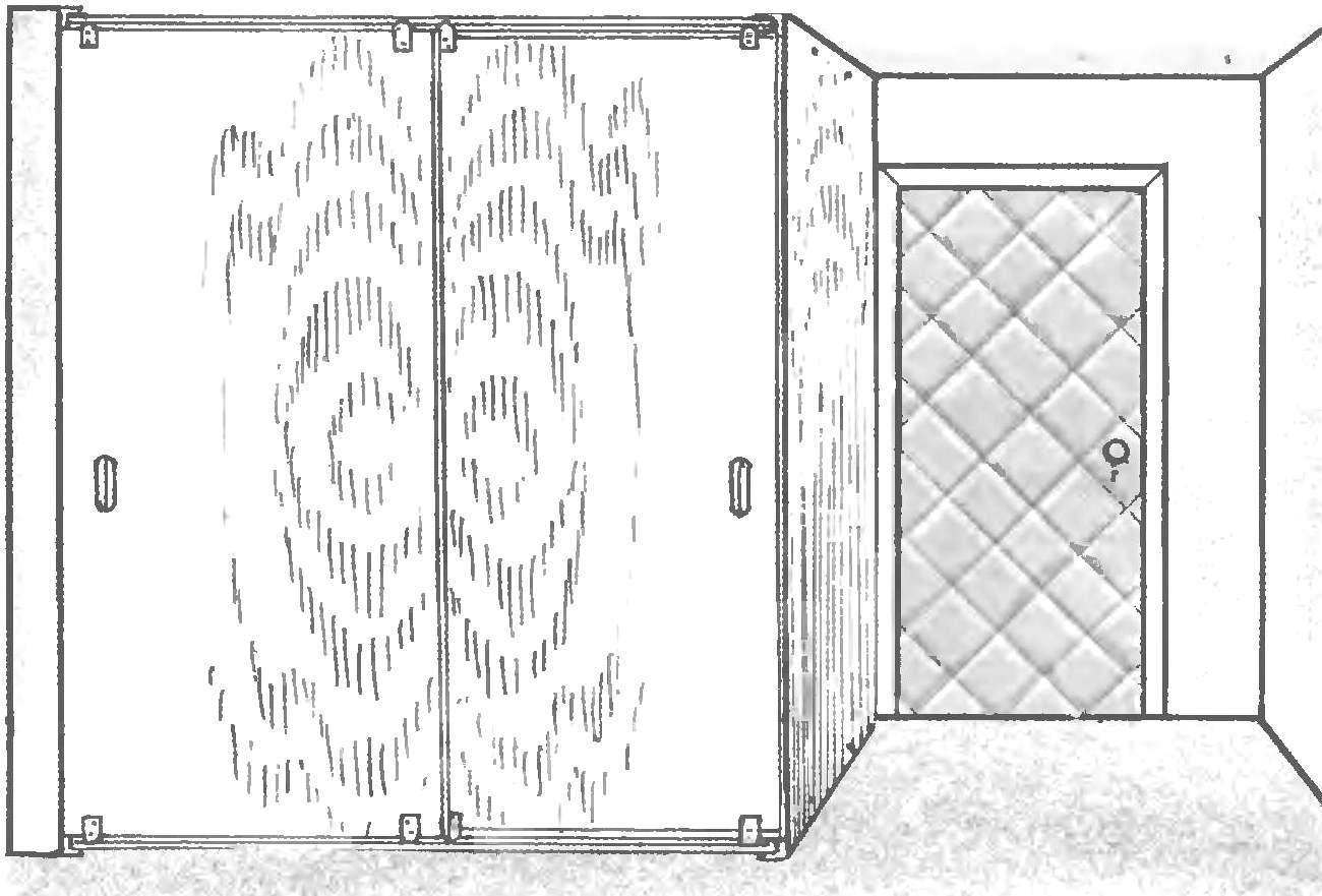
General view of the wardrobe
The angular cross member of the frame is made from a steel angle 25x25x3 mm. In length they are the same as the wall interior partitions, which serves as a sidewall of the Cabinet. Stepping back from the front edge the door thickness (16 mm) to the horizontal shelves each of the four cross members welded nut M8 for fastening the first guide. The center of the nut coincides with a line indent. Then, moving inside a further distance equal to the length of the roller axis plus a gap of 3 — 5mm, welded another nut like this for the next guide. Between the nuts, and then along the length of the cross members in the horizontal shelves of angles approximately equidistant from each other about-swarley three holes with a diameter of 5 mm for fixing parts to the floor and ceiling of the apartment building with steel dowels. In vertical shelves of the two cross members made of threaded holes M8 — with their help, screws with countersunk heads to the cross members is attached to the side panel.
But before you mount the crossmember in place, it is necessary to check the levelness of the floor and ceiling. If there are deviations in the appropriate places under the corners need to enclose a strip to at least their front ends were on the same level. This is necessary in order to ensure the horizontal top and bottom rails (except perhaps spontaneous rolling doors, and even falling out of the top of the guide).
Guides (there are four: two upper and two lower) is identical to each other. They are made of steel pipes with outer diameter 17 mm with a wall thickness of 2.8 mm the pipe Ends on the length equal to the width of the inner part of the shelf area of the cross-arms cut to a depth equal to the sum of the thickness of the shelf area and the height of the nut (but better less than 1 mm). The ends of the guides drilled holes 8.5 mm diameter bolt
If work on the installation frame are performed with an assistant to “catch” millimeters (and it should be done in the execution of all operations), you can first connect the rails with crossbars, and the last pin dowels on the floor and the ceiling.
Roller mechanism — the private development, be possible to make yourself in a home workshop. It consists of a pair of identical cheek with a jumper between them and the roller axis. In addition to these elements the mechanism used two standard parts: washer and cotter pin. Axle made from a long M8 bolt, who cut off the threaded part.
Cheeks are made of steel plate with a thickness of 3 mm. each drilled hole with a diameter of 8 mm for the axle and made three slits: two vertical for the mounting screws and one horizontal — it is inserted into the shelf jumper Slots for screws offset from each other and arranged like a checkerboard pattern. This eliminates the penetration of the screws into one another when screwing them inside and out, it is only necessary when you build the site to be carefully and properly install the opposite cheek. The length of the slotted screws allows to the extent necessary to adjust the tilt of the door (to eliminate their bias and gaps between their vertical edges and side walls) install shims between the bulkhead and the bottom edge. The jumper is made from the same plate, and cheeks.
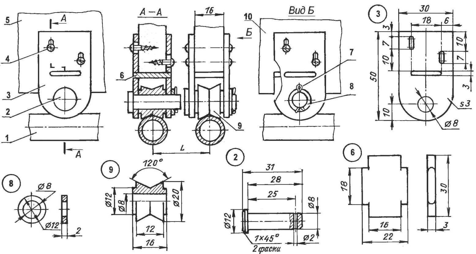
Roller mechanism:
1 — guide; 2 — axis (modified steel M8 screws); 3 — cheek (steel sheet s3. 2); 4 – 15×3 screw (4 PCs); 5 – painting exterior doors (chipboard); 6 — jumper (sheet s3), 7 — cotter pin Ø2. 8 – washer 12x8x2; 9 — the roller (scal, circle Ø20); 10 — leaf interior doors
The roller is made of steel billet thickness, as the door of 16 mm and a diameter of 20 mm., This diameter I found to be optimal.
Below the video is not off the round tubular guide, its rim performed with a triangular recess. It would be possible to make the concave profile radius of the tube, but the clip with the triangular rim is universal and fits any diameter of the guide.
Developing roller gear, I was planning a jumper to the cheek weld — so it would be easier to make the knot. But then the connection was sealed, and this would greatly complicate the installation of doors in the doorway, as I wanted to reduce the gap between the horizontal edges of the doors and guides you to choose a recess in the chipboard under the roller mechanisms. But in fact, these grooves do not necessarily. You can cover the gap with strips, attaching them to the lower and upper edges of the doors.
The axis of the roller, as already mentioned, made of M8 screws: the rod is cropped to the required size and at the end of the drilled cross hole for a cotter pin, head height reduced by half, her ribs under the worn key. After Assembly of the mechanism on the axis from the inner cheek, put on a washer and fixed pin. The axle can be made of tubes, rezvantseva one edge and whereby the collar and the other to drill into the walls of the holes for the cotter pin. To mount the roller mechanisms on the door should be no closer than 50 mm from the edges.
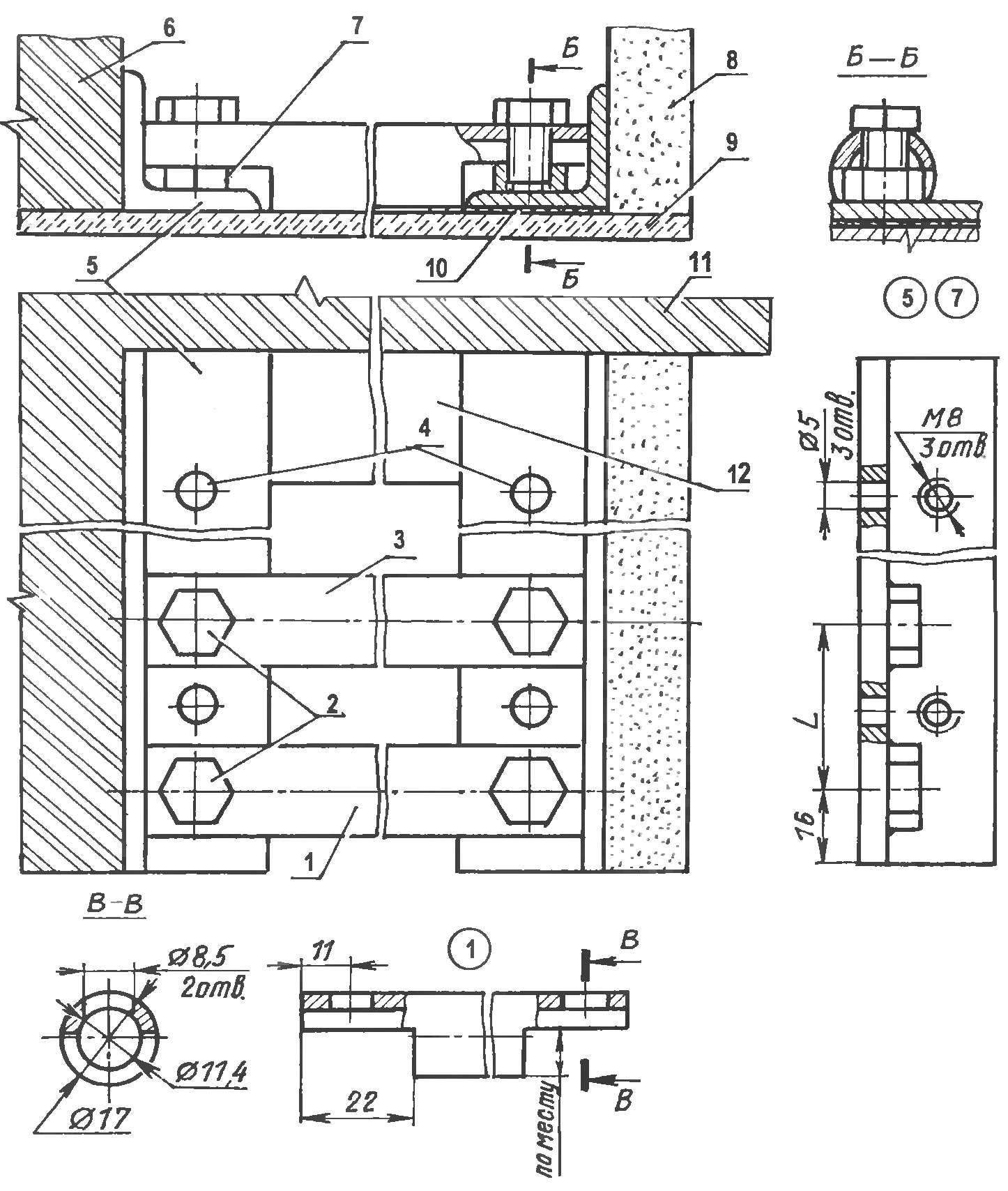
Support structure:
1,3 — outer and inner guide rails (steel pipe 17×2,8); 2 — mount rails (bolt M8 L12,4 PCs.); 4 — fastening of the cross members (construction dowels, 3 pieces onto the crossbars), 5 — cross member (steel angle 25x25x3, 2); 6 — room bulkhead; 7 – nut M8 extended (4x); 8 the side panel of the Cabinet (particleboard, s12); the 9 — floor (ceiling); 10, seal; 11, the wall of the apartment; 12 — skirting
My wardrobe two-door. Doors, internal and external, of the same size, but when you assign their width must be considered in the closed position (one in left, another in the extreme right) they should overlap in the middle 50 — 70 mm. height of the door such that the top and bottom between their horizontal edges and the guide remained at least 5-mm gap. It is necessary for ventilation of the inner volume of the enclosure, for adjusting misalignment of the doors and their smooth movement. Both fold — out chipboard (particle Board), 16 mm thick — it is sufficient if the height of the room up to three meters. Well, when the sheets of particle Board is smooth, if they curved, they should be set so that the bulges were not directed towards each other — otherwise, the sash can hurt one for another. The handle on the door is better not to put — they will prevent full opening of doors. Instead, the door panels, it is advisable to cut slits in the arm at a height of 1200-1300 mm. the Side wall of the Cabinet — from the same sheet of chipboard, and doors, but you can use thinner sheet and, provided that there will be no bearing on a large number of shelves.
If the width of the door panels does not allow to block the aperture two doors, it is possible to make a three-door wardrobe by placing on one of the guides (external or internal) from two doors.
In the case when the Cabinet is attached to the outer wall of the house, between the horizontal edges of the doors and guide rails to improve the ventilation inside Cabinet space is necessary to leave gaps of 20 to 30 mm. Below the latter are not conspicuous, they can be covered from below with the nut, and above the cornice, is made along the entire length of the Cabinet.
The internal structure and decoration of the closet here do not quote everyone should decide this question individually, in accordance with their needs and taste.
A. TIMOFEEV, Blagoveshchensk, Amur region
Recommend to read
 AUTOGRANT IN THE HOUSE
The use of automotive capacitive sensor for home security. Automotive sensors swing (vibration), RF and capacitor, responsive to the approach of people to the car or movement in the...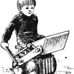 RIDING ON THE TRUCK
Even the ancients said that the child, playing, exploring the world. And with the advent of various kinds of mechanical toys, followed by electric and electronic (signs century...
